the12volt.com spacer
icon

custom door unlock requirement


Post ReplyPost New Topic
< Prev Topic Next Topic >
yippieguy 
Member - Posts: 5
Member spacespace
Joined: September 26, 2007
Location: Ontario, Canada
Posted: September 26, 2007 at 12:02 PM / IP Logged  

hi all:

Thanks for keeping this board running. there is a huge amount  of great info in here.

I have searched through many posts and relay diagrams, but I've not yet found something that will do precisely the following. The problem is that my car auto-locks all doors, but does not auto unlock the passenger door., only the driver's.  There is no way around this using the car's programming. This was changed by the manufacturer in the next year's model.

GOAL: send a 12V - pulse to the "unlock all doors" wire in my door once ignition is killed. I tested this and grounding this wire will unlock both doors.

I have access to connections for 12v batt, 12V ignition, driver's doorlock motor, and ground in my driver's door now.  I'd like to put this device into the driver's door itself.

I need to 'approve' this auto-unlock process by getting either 1) Ignition for at least 30 seconds or 2) 12V from the driver's door having been locked electronically. Once "approved", meaning the driver's door has been locked by the car (At 15km/hr), or if ignition has been seen for at least 30 secs, .. then as soon as ignition is removed, send the pulse just once.

there it is.. any help would be most appreciated!

Thanks

J.

yippieguy 
Member - Posts: 5
Member spacespace
Joined: September 26, 2007
Location: Ontario, Canada
Posted: September 26, 2007 at 12:58 PM / IP Logged  

I'm replying to my own email to mention that I'm ok to use a DPDT relay to latch itself once it sees the driver's doorlock motor activate (goes 12v+ momentarily).. so that will handle the "approval" or "ok to auto-unlock doors later" phase...

next part is to give the 12v- pulse I seek, once ignition is removed.

thanks again all for any input (and 12- output) you can offer :)

J.

yippieguy 
Member - Posts: 5
Member spacespace
Joined: September 26, 2007
Location: Ontario, Canada
Posted: September 27, 2007 at 9:03 AM / IP Logged  
custom door unlock requirement -- posted image.
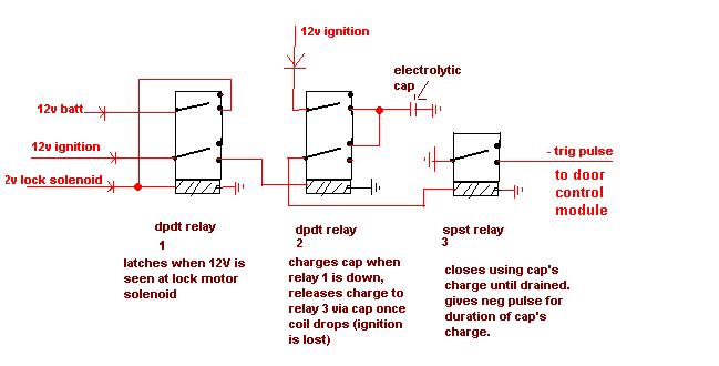
how's this look? it came to me this morning.. should be able to rebuild using transistors though - this is silly to use relays for a low-current circuit like this.. any suggestions/improvements/things I've missed?
thanks!
hotwaterwizard 
Silver - Posts: 1,350
Silver spacespace
Joined: December 11, 2003
Location: California, United States
Posted: September 28, 2007 at 8:19 AM / IP Logged  
custom door unlock requirement -- posted image.
John DeRosa (Hotwaterwizard)
Stockton California
When in doubt, try it out !
hotwaterwizard 
Silver - Posts: 1,350
Silver spacespace
Joined: December 11, 2003
Location: California, United States
Posted: September 28, 2007 at 8:20 AM / IP Logged  

Add that Circuit with a Constant to momentary and you got it.  Circuit modified for negitive pulse output.

custom door unlock requirement -- posted image.

John DeRosa (Hotwaterwizard)
Stockton California
When in doubt, try it out !
yippieguy 
Member - Posts: 5
Member spacespace
Joined: September 26, 2007
Location: Ontario, Canada
Posted: September 28, 2007 at 8:50 AM / IP Logged  
wow Hotwaterwizard.. thank you. I appreciate the help!
Looking this over though... the first 1/2 of this circuit (radio protector) would handle the delay portion, and would send 12v + to the 2nd portion after a few seconds of ignition being on; that part is cool. (And adjustable using different resistors and caps to extend that delay).   So far so good...
but then, the 2nd portion of the circuit (constant to momentary) would pulse a negative briefly to the door unlock portion as I see it, as soon as that delay had expired.
this would mean that after a few seconds of seeing ignition, the system would UNLOCK the doors, rather than waiting to LOSE ignition.
What has to happen here, is that that negative pulse is only to appear once, and briefly , once that 12V is LOST.   Have I mis-read something?
Thanks again!
hotwaterwizard 
Silver - Posts: 1,350
Silver spacespace
Joined: December 11, 2003
Location: California, United States
Posted: September 29, 2007 at 1:49 PM / IP Logged  

Power-Off Time Delay Relay http://ourworld.compuserve.com/homepages/Bill_Bowden/page2.htm

The two circuits below illustrate opening a relay contact a short time after the ignition or ligh switch is turned off. The capacitor is charged and the relay is closed when the voltage at the diode anode rises to +12 volts. The circuit on the left is a common collector or emitter follower and has the advantage of one less part since a resistor is not needed in series with the transistor base. However the voltage across the relay coil will be two diode drops less than the supply voltage, or about 11 volts for a 12.5 volt input. The common emitter configuration on the right offers the advantage of the full supply voltage across the load for most of the delay time, which makes the relay pull-in and drop-out voltages less of a concern but requires an extra resistor in series with transistor base. The common emitter (circuit on the right) is the better circuit since the series base resistor can be selected to obtain the desired delay time whereas the capacitor must be selected for the common collector (or an additional resistor used in parallel with the capacitor). The time delay for the common emitter will be approximately 3 time constants or 3*R*C. The capacitor/resistor values can be worked out from the relay coil current and transistor gain. For example a 120 ohm relay coil will draw 100 mA at 12 volts and assumming a transistor gain of 30, the base current will be 100/30 = 3 mA. The voltage across the resistor will be the supply voltage minus two diode drops or 12-1.4 = 10.6. The resistor value will be the voltage/current = 10.6/0.003 = 3533 or about 3.6K. The capacitor value for a 15 second delay will be 15/3R = 1327 uF. We can use a standard 1000 uF capacitor and increase the resistor proportionally to get 15 seconds.

custom door unlock requirement -- posted image.

http://ourworld.compuserve.com/homepages/Bill_Bowden/relay_i.gif

John DeRosa (Hotwaterwizard)
Stockton California
When in doubt, try it out !
hotwaterwizard 
Silver - Posts: 1,350
Silver spacespace
Joined: December 11, 2003
Location: California, United States
Posted: September 29, 2007 at 4:08 PM / IP Logged  

The circuit would look something like this.

Delay off with Pulse timer to follow

John DeRosa (Hotwaterwizard)
Stockton California
When in doubt, try it out !
yippieguy 
Member - Posts: 5
Member spacespace
Joined: September 26, 2007
Location: Ontario, Canada
Posted: October 04, 2007 at 4:26 PM / IP Logged  
Looks great. thank you so much once again for your help , hotwaterwizard!

Sorry, you can NOT post a reply.
This topic is closed.

  Printable version Printable version Post ReplyPost New Topic
You cannot post new topics in this forum
You cannot reply to topics in this forum
You cannot delete your posts in this forum
You cannot edit your posts in this forum
You cannot create polls in this forum
You cannot vote in polls in this forum

  •  
Search the12volt.com
Follow the12volt.com Follow the12volt.com on Facebook
Thursday, May 15, 2025 • Copyright © 1999-2025 the12volt.com, All Rights Reserved Privacy Policy & Use of Cookies
Disclaimer: *All information on this site ( the12volt.com ) is provided "as is" without any warranty of any kind, either expressed or implied, including but not limited to fitness for a particular use. Any user assumes the entire risk as to the accuracy and use of this information. Please verify all wire colors and diagrams before applying any information.

Secured by Sectigo
the12volt.com spacer
Support the12volt.com
Top
the12volt.com spacer