the12volt.com spacer
icon

constant to momentary + de energise


Post ReplyPost New Topic
< Prev Topic Next Topic >
cluck 
Member - Posts: 4
Member spacespace
Joined: November 15, 2007
Location: Australia
Posted: November 15, 2007 at 7:32 AM / IP Logged  

I've done a good search and read heaps of posts about momentary relay switching but I still can't find my answer.

My project requires a short pulse when 12v (ignition) is active. Activating the switch on my laptop docking station for car PC.

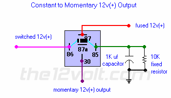
I've built the Constant to Momentary as per the diagram in Relays/Special Applications

constant to momentary + de energise -- posted image.

I'm not running any voltage across pin 30 to 87 - I just use it as a switch.

This works for the 1st time, but when I turn off and back on again the pulse becomes a constant. I think that the capacitor has not de-energised.

Am I right to think that the resistor is what de-energises the capacitor ? If I remove voltage from the coil for a while (5minutes)  the circuit works as planned.

So if I used a different resistor will that help de-energise the capacitor faster. Do I go for a higher number 10K to 100K or the other way 10K to 1K.

Is there any special direction for the capacitor (stripe side) or resistor (gold band end) ?

Or have I completly missed the idea of this circuit.

KPierson 
Platinum - Posts: 3,527
Platinum spaceThis member consistently provides reliable informationspace
Joined: April 14, 2005
Location: Ohio, United States
Posted: November 15, 2007 at 7:42 AM / IP Logged  

With a 10K ohm resistor I wouldn't think it would take 5 minutes to bleed the current off - how big is the cap?

Also, double check to make sure the resistor is brown, black, orange on the color band.

To bleed off current quicker use a smaller resistor (I would cut the value in half until you have reached an acceptable reset time.

Kevin Pierson
cluck 
Member - Posts: 4
Member spacespace
Joined: November 15, 2007
Location: Australia
Posted: November 15, 2007 at 8:05 AM / IP Logged  

Yep the rtesistor is Brown Black Orange - 1K resistance

The cap is 1000 uF.

I just read this post https://www.the12volt.com/installbay/forum_posts.asp~TID~98760~PN~1. Dunno why I missed  it before.

It ends with

you'll need to put a resistor on the input to ground, to discharge the cap after you open the switch, otherwise it won't reset for the next pulse.

how would that be achieved given the circuit I already have

KPierson 
Platinum - Posts: 3,527
Platinum spaceThis member consistently provides reliable informationspace
Joined: April 14, 2005
Location: Ohio, United States
Posted: November 15, 2007 at 9:28 AM / IP Logged  

brown black orange is 10k, not 1k.

The cap should be bleeding to ground through the resistor if the circuit is setup as shown, you shouldn't need any other resistors.

How long is your pulse?  You may try going with a smaller cap which will in turn shorten the amount of time it takes to discharge it.

Kevin Pierson
cluck 
Member - Posts: 4
Member spacespace
Joined: November 15, 2007
Location: Australia
Posted: November 16, 2007 at 2:05 AM / IP Logged  

Ah yes by bad. [:oops:]  I meant 10K - Everything is the same as the pic.

I've gone out and bought a range of resistors to try.

cluck 
Member - Posts: 4
Member spacespace
Joined: November 15, 2007
Location: Australia
Posted: November 16, 2007 at 2:24 AM / IP Logged  

Back from the lab. constant to momentary + de energise -- posted image.

I found that 220 works well. It takes less than 1 second to discharge the 1K cap.

Now to put it all onto a PCB board.


Sorry, you can NOT post a reply.
This topic is closed.

  Printable version Printable version Post ReplyPost New Topic
You cannot post new topics in this forum
You cannot reply to topics in this forum
You cannot delete your posts in this forum
You cannot edit your posts in this forum
You cannot create polls in this forum
You cannot vote in polls in this forum

  •  
Search the12volt.com
Follow the12volt.com Follow the12volt.com on Facebook
Tuesday, June 24, 2025 • Copyright © 1999-2025 the12volt.com, All Rights Reserved Privacy Policy & Use of Cookies
Disclaimer: *All information on this site ( the12volt.com ) is provided "as is" without any warranty of any kind, either expressed or implied, including but not limited to fitness for a particular use. Any user assumes the entire risk as to the accuracy and use of this information. Please verify all wire colors and diagrams before applying any information.

Secured by Sectigo
the12volt.com spacer
Support the12volt.com
Top
the12volt.com spacer