the12volt.com spacer
icon

neg doorlock output staying on continuos


Post ReplyPost New Topic
< Prev Topic Next Topic >
beanski 
Member - Posts: 6
Member spacespace
Joined: December 31, 2009
Location: New Brunswick, Canada
Posted: December 31, 2009 at 8:11 AM / IP Logged  

Hello        (I have a 1999 chev silverado)

I have put in a prostart ct-3471 tw car starter from Canadian Tire. I hooked up the unit, power door locks,and the arm- disarm feature. I like this thing alot ,it works great.

not sure if it was something I have done with the remote or if something else is going on. The door locks stoped working. when I checked the unit it is giving the neg output continuosly on on the lock and unlock pulse wires at same time. I have tried resetting the module with same results. 

The truck has positive outputs to locking unit.  I have used two relays to reverse polarity.The unit worked great for two or three weeks .Now this is happening but the rest of the unit is working ok .starting properly,security arming, just the locks are continuosly giving output .

I have removed the relays for now and just use the regular factory doorlock for now. any help would be great.

THANK YOU
Randy
tedmond 
Gold - Posts: 4,610
Gold spaceThis member has been recognized as an authority in Mobile Security and Convenience. Click here for more info.spacespace
Joined: January 06, 2007
Location: Ontario, Canada
Posted: December 31, 2009 at 2:48 PM / IP Logged  

looks like the on board circuit is burnt, it could be from an onrush current from the realys, if they were no diode was placed across the coils.

Ted
2nd Year Tier 1 Medical School
Still installing as a hobby...pays for groceries
Compustar Expert
beanski 
Member - Posts: 6
Member spacespace
Joined: December 31, 2009
Location: New Brunswick, Canada
Posted: December 31, 2009 at 3:21 PM / IP Logged  

Thanks for the reply. I guess I messed up .never tried putting one of these in before ,a bit of a challenge for myself.(didnt put in diode)

I suppose there is no way to open unit and repair damages? I have taken apart the four wheel drive selector last week and soldered cracks on the board and replaced all the bulbs in board of my gm radio .Thats the extent of MY electronics wondering if any components  could be unsoldered and replaced or is it massive damage when something cooks in these things? Just a thought,dont like giving in too easy.

Thanks again

THANK YOU
Randy
tedmond 
Gold - Posts: 4,610
Gold spaceThis member has been recognized as an authority in Mobile Security and Convenience. Click here for more info.spacespace
Joined: January 06, 2007
Location: Ontario, Canada
Posted: December 31, 2009 at 4:33 PM / IP Logged  
is the unit fairly new? if you still have the receipt to canadian tire, get it swapped.
Ted
2nd Year Tier 1 Medical School
Still installing as a hobby...pays for groceries
Compustar Expert
beanski 
Member - Posts: 6
Member spacespace
Joined: December 31, 2009
Location: New Brunswick, Canada
Posted: January 09, 2010 at 5:01 PM / IP Logged  

If I put the new unit in the vehicle. To prevent damage to unit again ,do I just put the diodes in between each pulse line coming from the unit and each relay that they are connected to .I am thinking this should stop the back feed or back rush of current from relays to the unit (as mentioned earlier posts). What kind of diodes should I get are there alot of different syles of them.12v for sure are there alot of different ratings .

Thanks

THANK YOU
Randy
howie ll 
Pot Metal - Posts: 16,466
Pot Metal spacespace
Joined: January 09, 2007
Location: United Kingdom
Posted: January 09, 2010 at 5:14 PM / IP Logged  
Place the diodes across the coil terminals of the relay, between 85 and 86.
Assuming your lock trigger goes to one side and a live feed goes to the other, place the diode band towards the pos. Use a 1N4004 from Radio Shack, one for each relay. Solder the diodes across the terminals, one to each relay.
beanski 
Member - Posts: 6
Member spacespace
Joined: December 31, 2009
Location: New Brunswick, Canada
Posted: January 09, 2010 at 8:49 PM / IP Logged  

Both of these are probably dumb questions to but here it goes.

can I just solder the diodes onto the 85 and 86 pigtails that came with relays or does the diode have to be soldered directly onto the relay. 

second wont the power back feed through the coil itself even though the diode is above it on the terminals  .

sorry for this but I dont understand the power.  my unit pulse a neg12volt pulse on one terminal when activated on lock or unlock depending on what function used and the other is 12 all the time on the other.

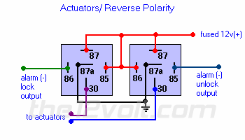
I have two relays side by side sharing a common 12v one on terminal 85 on one relay and 86 terminal on the other. then lock pulse and unlock pulse on either 86 or 85 terminal  other.   for the positive to the truck I have terminal 30 both for actuators .  terminal87 12volts on both  87a both grounds

THANK YOU
Randy
howie ll 
Pot Metal - Posts: 16,466
Pot Metal spacespace
Joined: January 09, 2007
Location: United Kingdom
Posted: January 10, 2010 at 2:32 AM / IP Logged  
From your description you've wired the reays wrong and burnt out the lock circuit on the alarm. You've continuously fed 12 volts back to the alarm
Lock output from alarm to 85
12volt constant power, fused at 5amps to 86 and 30
lock power output from 87.
Repeat for unlock.
Diodes on lock/unlock from from alarm, bands towards alarm.
Feed that 5amp fused to both relays.
beanski 
Member - Posts: 6
Member spacespace
Joined: December 31, 2009
Location: New Brunswick, Canada
Posted: January 10, 2010 at 9:38 AM / IP Logged  

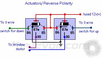
I have a hard time to explain .so I founfd this from apost of Jon 720 (doorlock actuator with remote start)0ct28 ,2009. It is exactly the way I have done it, maybe this will help then you will know how I am looking to put in  diode .sorry if I am dumming out on you but... thanks

neg doorlock output staying on continuos -- posted image.

THANK YOU
Randy
i am an idiot 
Platinum - Posts: 13,709
Platinum spaceThis member consistently provides reliable informationspace
Joined: September 21, 2006
Location: Louisiana, United States
Posted: January 10, 2010 at 10:00 AM / IP Logged  
neg doorlock output staying on continuos -- posted image.
Page of 2

  Printable version Printable version Post ReplyPost New Topic
You cannot post new topics in this forum
You cannot reply to topics in this forum
You cannot delete your posts in this forum
You cannot edit your posts in this forum
You cannot create polls in this forum
You cannot vote in polls in this forum

  •  
Search the12volt.com
Follow the12volt.com Follow the12volt.com on Facebook
Wednesday, May 14, 2025 • Copyright © 1999-2025 the12volt.com, All Rights Reserved Privacy Policy & Use of Cookies
Disclaimer: *All information on this site ( the12volt.com ) is provided "as is" without any warranty of any kind, either expressed or implied, including but not limited to fitness for a particular use. Any user assumes the entire risk as to the accuracy and use of this information. Please verify all wire colors and diagrams before applying any information.

Secured by Sectigo
the12volt.com spacer
Support the12volt.com
Top
the12volt.com spacer