the12volt.com spacer
icon

avital 5103 on nissan altima 99


Post ReplyPost New Topic
< Prev Topic Next Topic >
ceco134 
Member - Posts: 4
Member spacespace
Joined: August 17, 2012
Location: Indiana, United States
Posted: August 17, 2012 at 5:37 PM / IP Logged  
Hello guys.
I have a problem with my Avital 5103 remote starter,just installed.I had the unit purchased on May ,but I did not have time to do the installation.So I installed by myself,test all of the features,worked fine.But in the morning the engine did not start remotely as expected.Tried to reprogram the unit,using Vallet/Program switch.Played around with menu 3.1,tried all 4 options: VirtualTach,Voltage,OFF,Tachometer.None of them worked when the engine is cold.All them works when the engines is a bit warm.Tried to increase crank time to max 4.0,did not help.Tried to use tach learn signal option,programmed 1200 rpm,did not work.I was really disappointed from this unit,cause expected more .Finally decided to contact Avital support,found the closest dealer,called and when the dealer figured out,that I need support,not going to buy anything,from them,just dropped the phone.Tried to reach another closest dealer by email and phone-no answer so far.Any help from you guys will be appreciated.Car is Nissan Altima 2.4L 1999.I assume that every necessary wire,include the tach one is connected in proper order,either way remote starter would not work,if the engine is a bit warm.
Thank you in advance
kreg357 
Platinum - Posts: 7,789
Platinum spaceThis member has made a donation to the12volt.com. Click here for more info.spaceThis member has been recognized as an authority in Electrical Theory. Click here for more info.spaceThis member has been recognized as an authority in Mobile Security and Convenience. Click here for more info.spacespace
Joined: January 30, 2009
Location: Pennsylvania, United States
Posted: August 17, 2012 at 6:28 PM / IP Logged  

Verify that the Starter2 wire is properly connected & powered during remote start.

STARTER 2   BLACK/ BLUE (+) See NOTE *1    IGNITION SWITCH HARNESS

 NOTE *1 When Installing a REMOTE STARTER, you MUST use BOTH Starter #1 and Starter #2 wires. Both wires must be connected

 to the STARTER/CRANKING Output wires from the Remote Starter or the vehicle will NOT Remote Start when the Engine is cold.
 (Starter2 wire is known as "fuel enrichment".)

Soldering is fun!
ceco134 
Member - Posts: 4
Member spacespace
Joined: August 17, 2012
Location: Indiana, United States
Posted: August 17, 2012 at 7:43 PM / IP Logged  
kreg357 wrote:

Verify that the Starter2 wire is properly connected & powered during remote start.

STARTER 2   BLACK/ BLUE (+) See NOTE *1    IGNITION SWITCH HARNESS

 NOTE *1 When Installing a REMOTE STARTER, you MUST use BOTH Starter #1 and Starter #2 wires. Both wires must be connected

 to the STARTER/CRANKING Output wires from the Remote Starter or the vehicle will NOT Remote Start when the Engine is cold.
 (Starter2 wire is known as "fuel enrichment".)

Thank you for your fast reply.I just checked my installation,I did not connect that wire unfortunately.Just did it.Will see how it works in the morning.My concern is why they use 2 starters wires,but I`ve got only 1 output in Avital starter module.I connected them together and I`m not sure is that going to overload the system if it designed to work with 2 wires and I made them as one.
Thank you!
ceco134 
Member - Posts: 4
Member spacespace
Joined: August 17, 2012
Location: Indiana, United States
Posted: August 17, 2012 at 7:53 PM / IP Logged  
ceco134 wrote:
kreg357 wrote:

Verify that the Starter2 wire is properly connected & powered during remote start.

STARTER 2   BLACK/ BLUE (+) See NOTE *1    IGNITION SWITCH HARNESS

 NOTE *1 When Installing a REMOTE STARTER, you MUST use BOTH Starter #1 and Starter #2 wires. Both wires must be connected

 to the STARTER/CRANKING Output wires from the Remote Starter or the vehicle will NOT Remote Start when the Engine is cold.
 (Starter2 wire is known as "fuel enrichment".)

Thank you for your fast reply.I just checked my installation,I did not connect that wire unfortunately.Just did it.Will see how it works in the morning.My concern is why they use 2 starters wires,but I`ve got only 1 output in Avital starter module.I connected them together and I`m not sure is that going to overload the system if it designed to work with 2 wires and I made them as one.
Thank you!
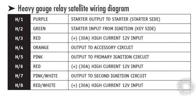
avital 5103 on nissan altima 99 -- posted image.
kreg357 
Platinum - Posts: 7,789
Platinum spaceThis member has made a donation to the12volt.com. Click here for more info.spaceThis member has been recognized as an authority in Electrical Theory. Click here for more info.spaceThis member has been recognized as an authority in Mobile Security and Convenience. Click here for more info.spacespace
Joined: January 30, 2009
Location: Pennsylvania, United States
Posted: August 17, 2012 at 8:21 PM / IP Logged  

Nissan designed that circuit to be separate for some reason.  The 5103 should allow you to program the H7 Pink/White wire as Starter2

and connect it to the vehicles Starter2 wire.  Just make sure all three Red power input wires ( H3, H6 & H8 ) are connected to a suitable
+12V constant source.

Additionally, if the starter re-engages during a key-take-over after remote start up, you will need to isolate the vehicles Accessory

wire from the ignition switch during remote start.  Here is that info from DEI :

When doing remote start, this wire must be isolated from the key switch with the accessory relay. See Tech Doc 1077 for wiring information.

https://www.the12volt.com/installbay/file.asp?ID=1060        See Page 2 for diagram.

Soldering is fun!
howie ll 
Pot Metal - Posts: 16,466
Pot Metal spacespace
Joined: January 09, 2007
Location: United Kingdom
Posted: August 18, 2012 at 1:13 AM / IP Logged  
Or diode* out GWR (Status)wire and use a relay thus:-
GWR to 85.
20amp fused constant to 86 and 87.
30 to second starter.
1N4004 diode between 85 and 86, band to 86.
* Diode (1N40004)required only if that GWR wire is also used for something else.
BTW Kregg, the Rover had FOUR ignitions, one more than it's step-brother the 5 Series!
ceco134 
Member - Posts: 4
Member spacespace
Joined: August 17, 2012
Location: Indiana, United States
Posted: August 18, 2012 at 7:34 PM / IP Logged  
Worked great.That was caused my problem-starter 2 wire was not connected.Thank you for all replies guys.I really appreciated!

Sorry, you can NOT post a reply.
This topic is closed.

  Printable version Printable version Post ReplyPost New Topic
You cannot post new topics in this forum
You cannot reply to topics in this forum
You cannot delete your posts in this forum
You cannot edit your posts in this forum
You cannot create polls in this forum
You cannot vote in polls in this forum

  •  
Search the12volt.com
Follow the12volt.com Follow the12volt.com on Facebook
Friday, May 31, 2024 • Copyright © 1999-2024 the12volt.com, All Rights Reserved Privacy Policy & Use of Cookies
Disclaimer: *All information on this site ( the12volt.com ) is provided "as is" without any warranty of any kind, either expressed or implied, including but not limited to fitness for a particular use. Any user assumes the entire risk as to the accuracy and use of this information. Please verify all wire colors and diagrams before applying any information.

Secured by Sectigo
the12volt.com spacer
Support the12volt.com
Top
the12volt.com spacer