the12volt.com spacer
icon

viper keyless w/ aftermarket actuators


Post ReplyPost New Topic
< Prev Topic Next Topic >
webergrey623 
Member - Posts: 3
Member spacespace
Joined: May 22, 2013
Location: Texas, United States
Posted: May 22, 2013 at 9:43 PM / IP Logged  
Ok so I got a $30 keyless kit for my 2-door F150 from eBay, and it blew out after one day. They sent me another and it didn't work at either. But I kept the door actuators installed thinking maybe they'll fare a little better.
Anyway, this time I got a Viper 211HV keyless unit to put in there (them no-names weren't making it). The wiring on the others were real simple, just two wires, a green and a blue, going to the 2 actuators in parallel. On the Viper though, there's 4 wires, a Lock-N/O, Unlock-N/O, a Lock-Common and an Unlock-Common. There's also an Unlock-N/O wire and a Lock-N/C wire, that are inputs. I assume these are for using your factory remotes or something if you've got some?
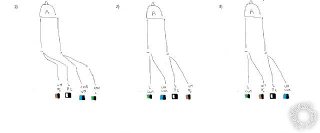
So anyway I've got this rough sketch of the 4 wires that I think are used with their color codes and an actuator marked "A" at the top. And I was just wondering which one of the drawings would be the right way to wire it, if any are correct. I've tried different combinations and haven't gotten an actuator to fire yet, so I must be overlooking something. I can hear the relays in the Viper clicking though when I hit the remote. Thanks a lot!
viper keyless w/ aftermarket actuators -- posted image.
howie ll 
Pot Metal - Posts: 16,466
Pot Metal spacespace
Joined: January 09, 2007
Location: United Kingdom
Posted: May 23, 2013 at 12:33 AM / IP Logged  
Violet and violet/black to 12V constant.
WHITE/ black and BROWN / black to ground.
Blue/black and GREEN/ black to actuators.
webergrey623 
Member - Posts: 3
Member spacespace
Joined: May 22, 2013
Location: Texas, United States
Posted: May 23, 2013 at 1:11 AM / IP Logged  
Aaah ok, so this is different than that other I installed. It just had 2 powered relay output wires that did everything and this one has to be supplied the power to the relays on those other wires. I was thinking it might be something like that going on. I had a Micro keyless that was just the 2 wires too so this type I hadn't ever dealt with before. -Appreciate it
howie ll 
Pot Metal - Posts: 16,466
Pot Metal spacespace
Joined: January 09, 2007
Location: United Kingdom
Posted: May 23, 2013 at 1:21 AM / IP Logged  
Two lock wires usually means direct low current transistor outputs and you must add relays for direct control.
With 6 wires the relays will be internal.
That's why you burnt out the $30 units.
webergrey623 
Member - Posts: 3
Member spacespace
Joined: May 22, 2013
Location: Texas, United States
Posted: May 23, 2013 at 1:52 AM / IP Logged  
I wondered that too but the wiring diagram never showed any extra relays in circuit, just direct to the actuators. But yeah I probly screwed something up. The actuators in the front doors have 2 extra wires, a brown one and a white one, that are going to a grounded DPST switch in the diagram. Not sure what that's about. Seemed like they fired ok for a little while without hooking them up to anything. This is on the $30 kit. I know when I took the head unit apart there were some transistors but also 2 micro relays in there.
So if I fried em what would be the thing to replace, the transistors probably?
howie ll 
Pot Metal - Posts: 16,466
Pot Metal spacespace
Joined: January 09, 2007
Location: United Kingdom
Posted: May 23, 2013 at 1:57 AM / IP Logged  
The $30 unit probably isn't worth repairing.
The two extra wires were "earth" (ground) going switching triggering what would appear to be internal relays as you suggested.
They are used either in conjunction with a momentary SPCO switch or with a 5 wire motor in the driver's door the three extra wires correspond to that switch (plus a ground connection).

Sorry, you can NOT post a reply.
This topic is closed.

  Printable version Printable version Post ReplyPost New Topic
You cannot post new topics in this forum
You cannot reply to topics in this forum
You cannot delete your posts in this forum
You cannot edit your posts in this forum
You cannot create polls in this forum
You cannot vote in polls in this forum

  •  
Search the12volt.com
Follow the12volt.com Follow the12volt.com on Facebook
Monday, July 7, 2025 • Copyright © 1999-2025 the12volt.com, All Rights Reserved Privacy Policy & Use of Cookies
Disclaimer: *All information on this site ( the12volt.com ) is provided "as is" without any warranty of any kind, either expressed or implied, including but not limited to fitness for a particular use. Any user assumes the entire risk as to the accuracy and use of this information. Please verify all wire colors and diagrams before applying any information.

Secured by Sectigo
the12volt.com spacer
Support the12volt.com
Top
the12volt.com spacer