Hi, indeed there are several topics already with the damn 323 or Protegé (depending on which country are you).
Straight to the point, I don't have a fancy alarm, is one of those

chinese ones. I bought it in a hurry since I just bought the car and it did not have any kind of protection system besides the door locking system.
Now, I did mess up before even finding you guys, because I had the service manual of the car and the wiring diagram, spent 2 days planning and supposedly all was going to be easy... for a 6ft tall person is not easy to install an alarm, specially in tight spaces.
Anyways, so, what I had thought was to tap to the door actuator from the door control system and that would be it...
WRONG. As many times I had read now, this is a one wire system, the thing is, which is the wire and how do I wire it?
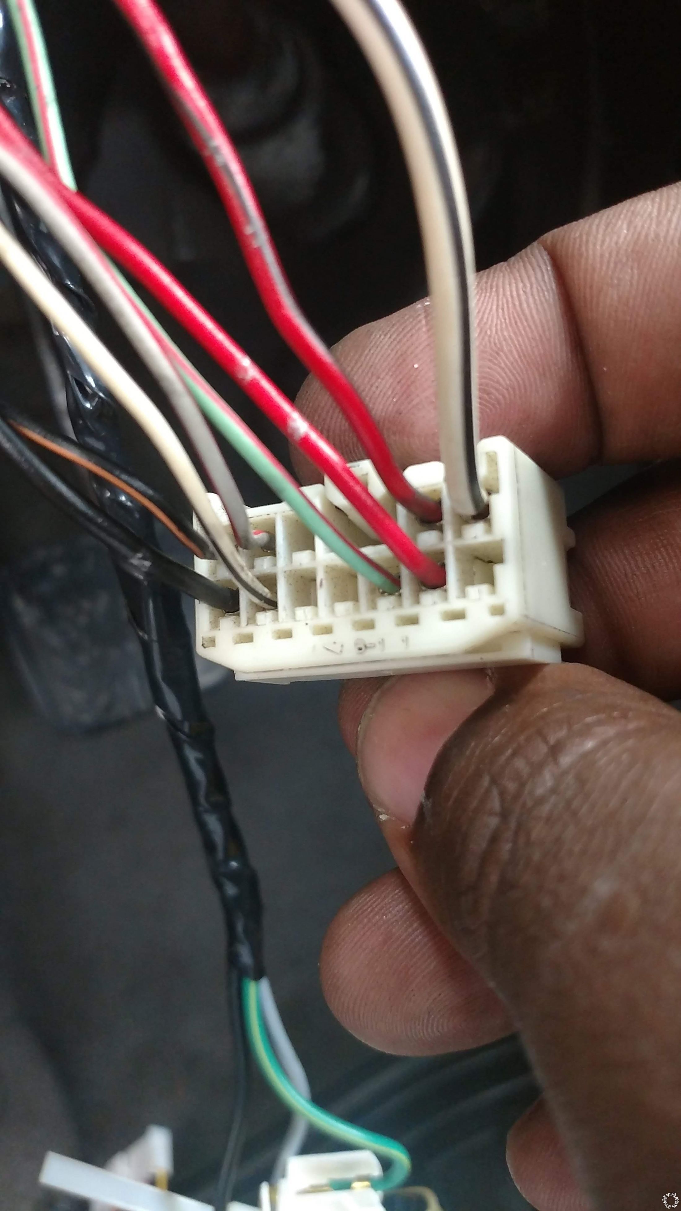
As you can see, this model does not seem to be completely the same as the US model.
Next, is what I had in mind, but is it
WRONG, using creates some short and the wires start to get hot also.
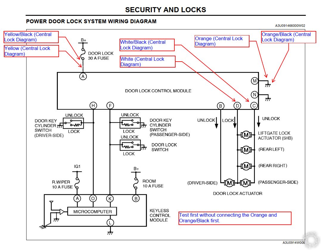
The thing is that, the diagram above, does not match the non-US model, since I'm missing pins: B, H, I, J. I know some are not there because I do not have the factory alarm.
The problem so far for the door locking,
pin K show 5V when locked and 0V when open, and pin L show 5V when open and 0V when closed.. Those pins appear as empty on the wiring diagram in the service manual.
Pin F does not show anything, I mean literally no voltage or something like 0.1 when actuating the driver side door lock, so I do not know how to interpret this. Is this the ONE-WIRE that I'm supposed to tag into? could it be pin F (green/red wire?)
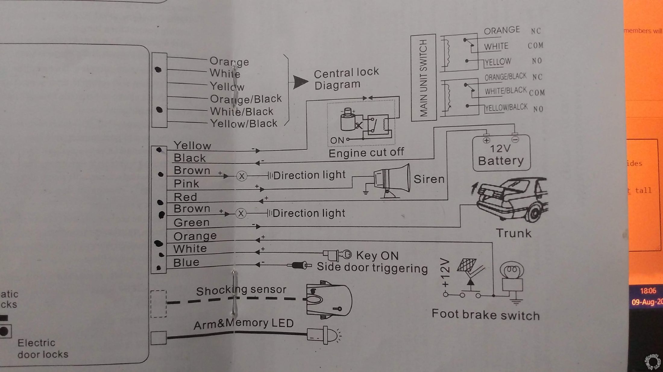
Moving forward, this is the diagram that I have from the alarm that I bought, again, sorry indeed, just a cheap china made, I promise to change it for a better brand name next year.
And a close up of the wiring of the door locking from the alarm side:
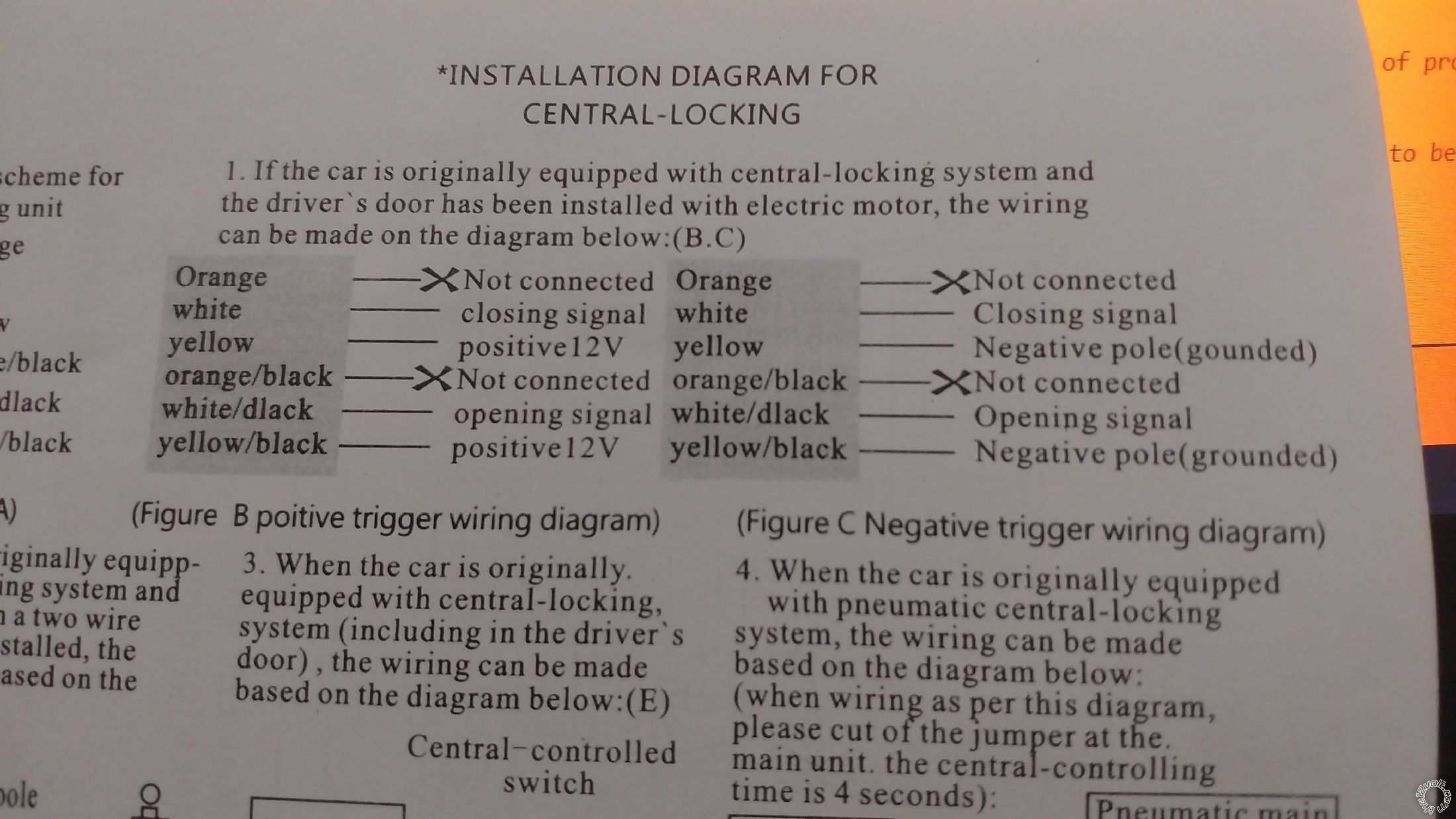
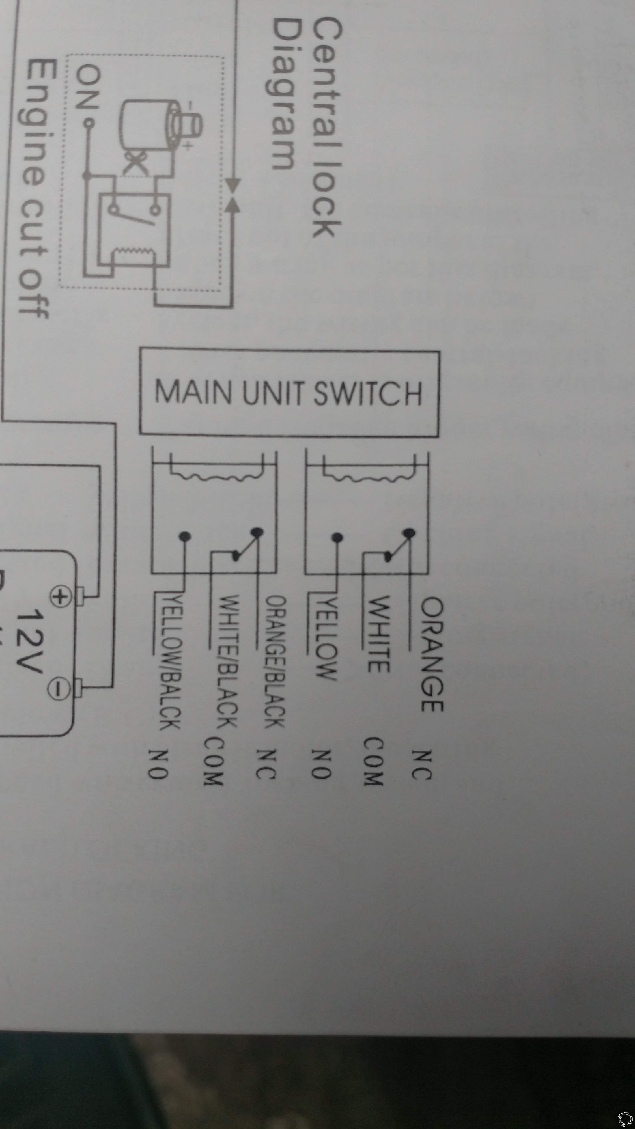
Now, I see that you guys mentioned an 1500 ohm resistor, the next question is: which wire is the trigger of the door? and how do I solder this resistor to the signals of the alarm?
I also see this diagram:
JBS alarm diagram one wire system
And this one:
Bulldog diagrams
I going to suppose that for the closing signal (white wire on the alarm) goes to the one-wire WITH resistor and the opening signal (white black wire on the alarm) goes WITHOUT resistor to the one-wire. The question is, where is this one-wire? could it be that one that showed 0.1v?
So far I have wired most of the stuff of the alarm, and so far I have to wire the door locking, the door trigger (which I know is a black blue wire but... I need to disassemble more since I do not fit quite in there... you know... 6ft tall here.
 Printable version


 chinese ones. I bought it in a hurry since I just bought the car and it did not have any kind of protection system besides the door locking system.
Now, I did mess up before even finding you guys, because I had the service manual of the car and the wiring diagram, spent 2 days planning and supposedly all was going to be easy... for a 6ft tall person is not easy to install an alarm, specially in tight spaces.
Anyways, so, what I had thought was to tap to the door actuator from the door control system and that would be it... WRONG. As many times I had read now, this is a one wire system, the thing is, which is the wire and how do I wire it?
 As you can see, this model does not seem to be completely the same as the US model.
Next, is what I had in mind, but is it WRONG, using creates some short and the wires start to get hot also.
 The thing is that, the diagram above, does not match the non-US model, since I'm missing pins: B, H, I, J. I know some are not there because I do not have the factory alarm.
The problem so far for the door locking, pin K show 5V when locked and 0V when open, and pin L show 5V when open and 0V when closed.. Those pins appear as empty on the wiring diagram in the service manual.
Pin F does not show anything, I mean literally no voltage or something like 0.1 when actuating the driver side door lock, so I do not know how to interpret this. Is this the ONE-WIRE that I'm supposed to tag into? could it be pin F (green/red wire?)
Moving forward, this is the diagram that I have from the alarm that I bought, again, sorry indeed, just a cheap china made, I promise to change it for a better brand name next year.
 And a close up of the wiring of the door locking from the alarm side:

 Now, I see that you guys mentioned an 1500 ohm resistor, the next question is: which wire is the trigger of the door? and how do I solder this resistor to the signals of the alarm?
I also see this diagram:


