


 Here's the tilt sensor diagram.
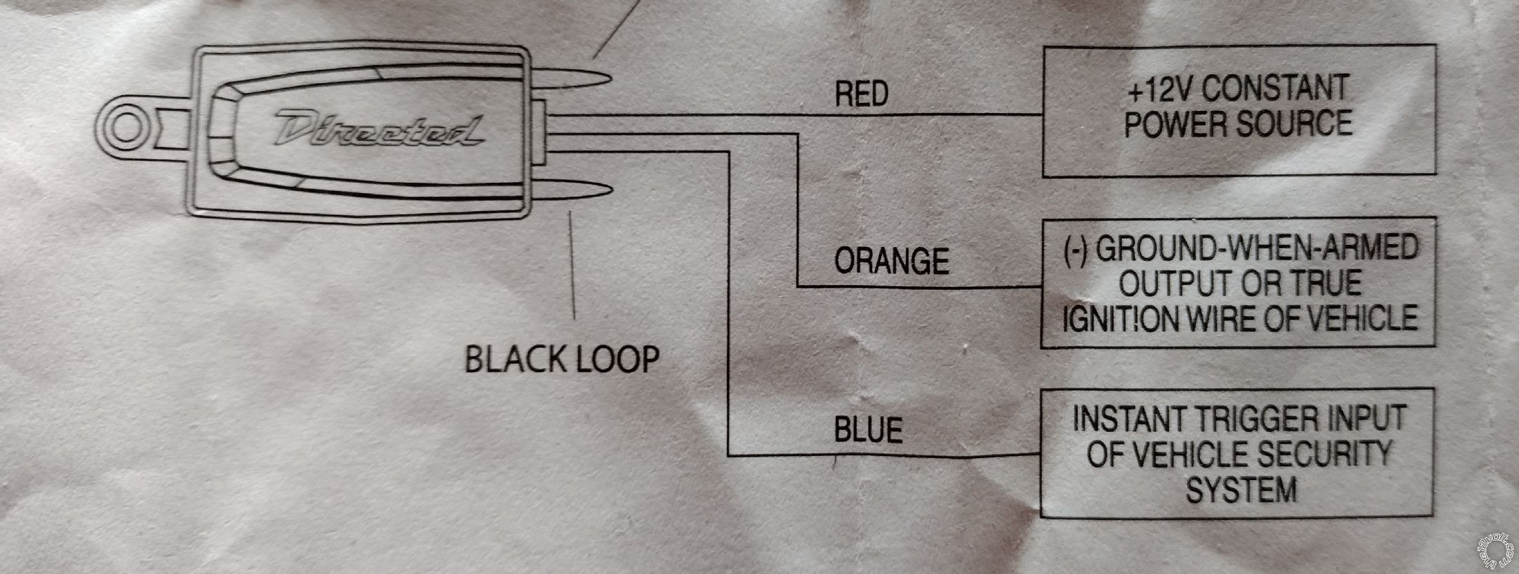 Would it just go like:
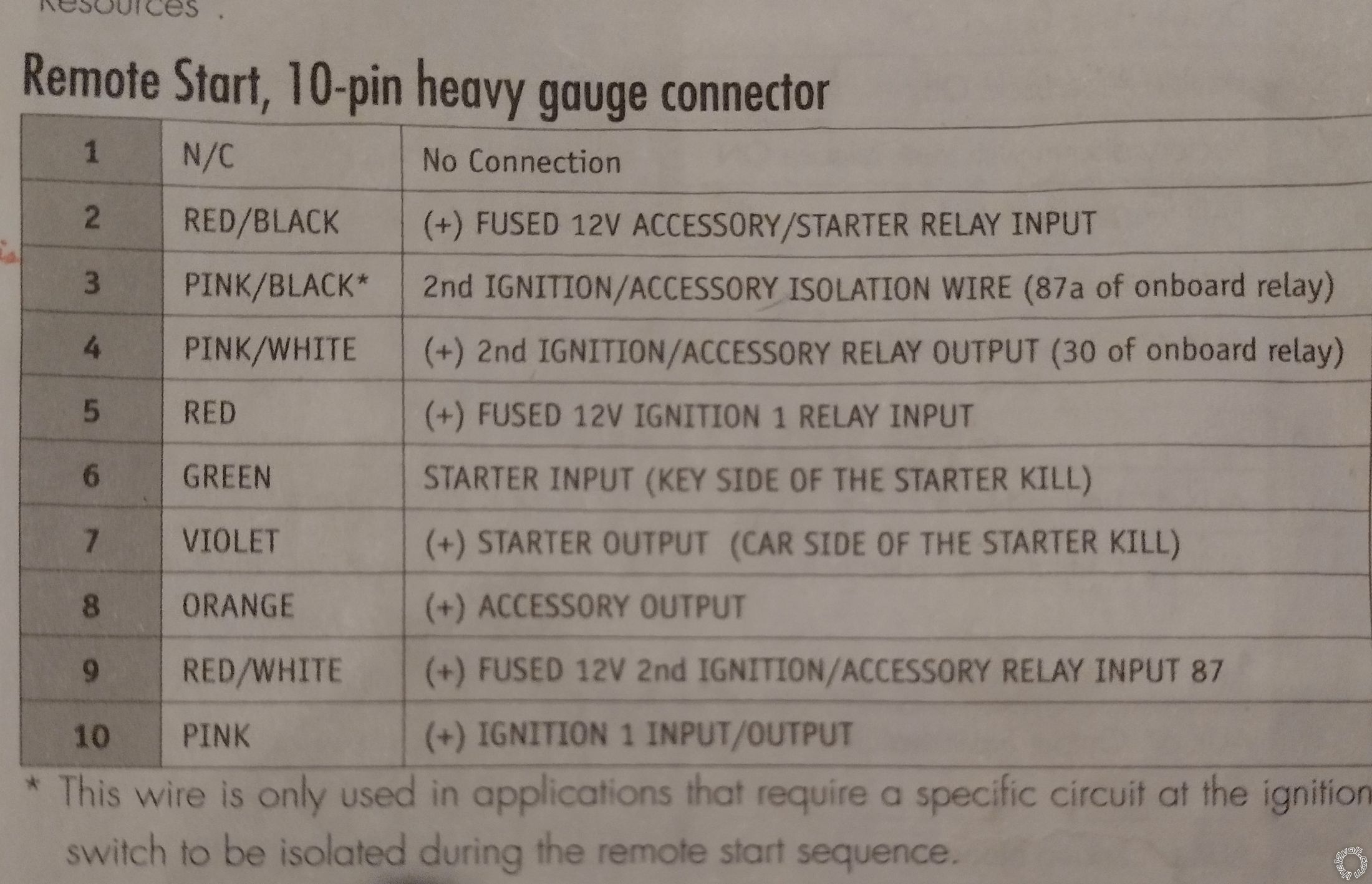
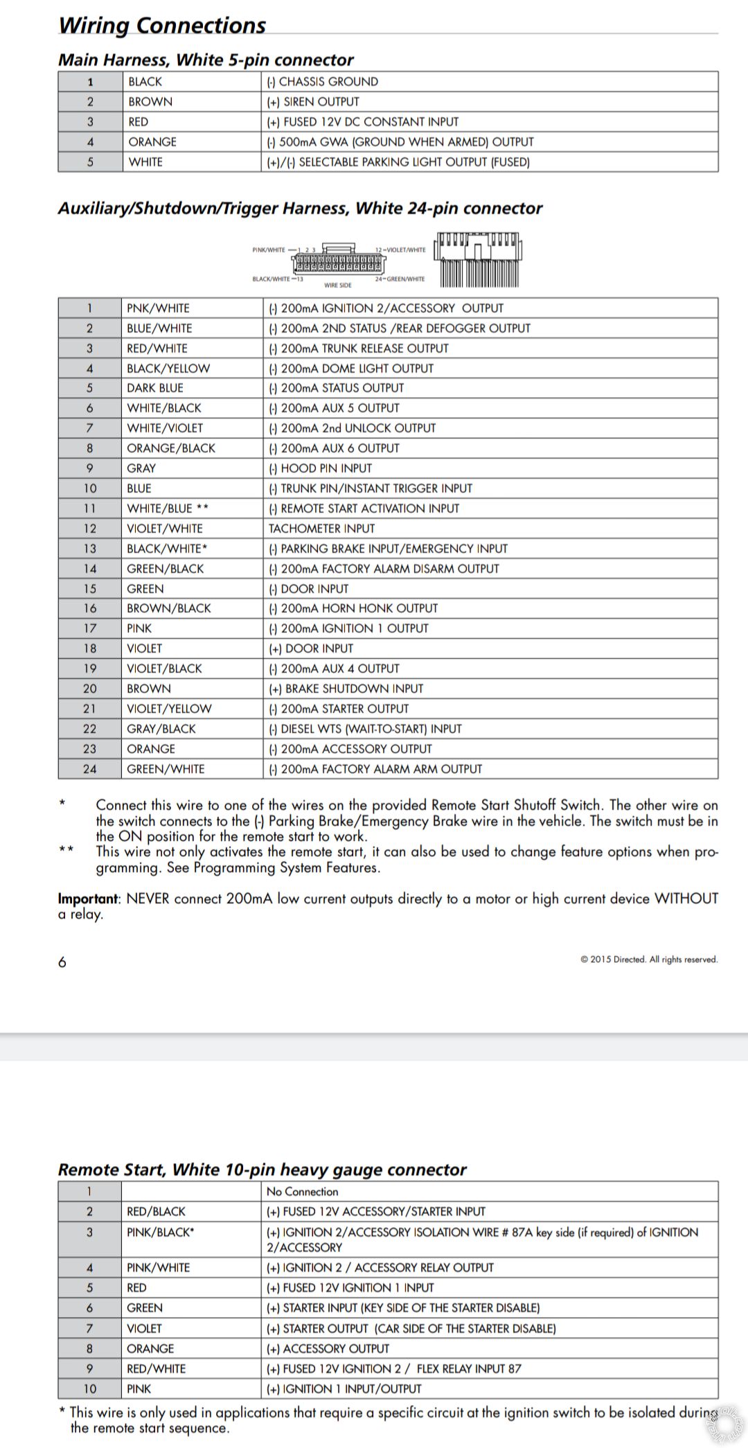
red to #3 on main harness
orange to #4 on main harness
blue to #10 on aux harness (diode in between and stripe towards alarm brain)
The backup battery diagram shows what I think is another diode in line with the brain's constant power wire. If so, I assume the cathode stripe is to be on the side of the alarm?
Would it just go like:
red to #3 on main harness
orange to #4 on main harness
blue to #10 on aux harness (diode in between and stripe towards alarm brain)
The backup battery diagram shows what I think is another diode in line with the brain's constant power wire. If so, I assume the cathode stripe is to be on the side of the alarm?
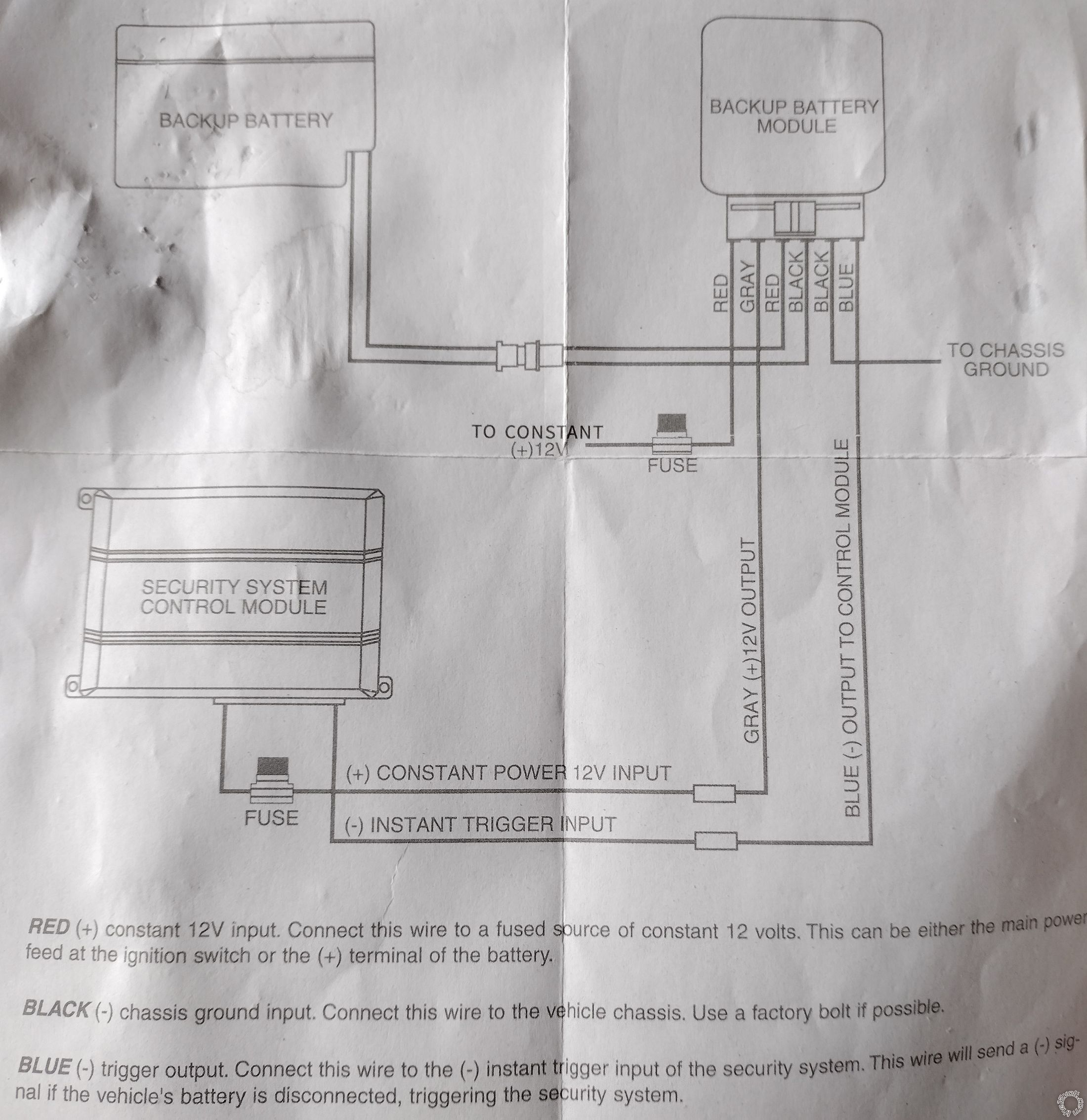 Do these connections for the battery backup seem right?
red to car battery positive
gray to #3 on main harness (diode in between and stripe towards alarm brain)
black to chassis ground
blue to #10 on aux harness (diode in between and stripe towards alarm brain)
Do these connections for the battery backup seem right?
red to car battery positive
gray to #3 on main harness (diode in between and stripe towards alarm brain)
black to chassis ground
blue to #10 on aux harness (diode in between and stripe towards alarm brain)

 You don't think it would be ok to tap into the main harness for power and GWA?
I'm thinking I can at least use #10 (blue) on the accessory harness for both of their triggers...
You don't think it would be ok to tap into the main harness for power and GWA?
I'm thinking I can at least use #10 (blue) on the accessory harness for both of their triggers...If you wish to post a reply to this topic, you must first login.
If you are not already registered, you must first register.
 Printable version


| You cannot post new topics in this forum You cannot reply to topics in this forum You cannot delete your posts in this forum You cannot edit your posts in this forum You cannot create polls in this forum You cannot vote in polls in this forum |

| Search the12volt.com |
Follow the12volt.com 
Friday, May 1, 2026 • Copyright © 1999-2026 the12volt.com, All Rights Reserved • Privacy Policy & Use of Cookies

Friday, May 1, 2026 • Copyright © 1999-2026 the12volt.com, All Rights Reserved • Privacy Policy & Use of Cookies
Disclaimer:
*All information on this site ( the12volt.com ) is provided "as is" without any warranty of any kind, either expressed or implied, including but not limited to fitness for a particular use. Any user assumes the entire risk as to the accuracy and use of this information. Please
verify all wire colors and diagrams before applying any information.
