the12volt.com spacer
icon

Door lock actuators hook up


Post ReplyPost New Topic
< Prev Topic Next Topic >
rad99 
Member - Posts: 8
Member spacespace
Joined: September 08, 2003
Posted: September 09, 2003 at 10:39 PM / IP Logged  
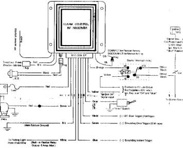
Hi, I sure hope you can help me. I have a 1985 Nissan 300zx.  I have installed a "Controller 1" alarm and most is working well except the door locks.  Alarm diagram has a 1 red and 1 black wire to "Optional doorlock module", so I bought a BDLM module. On alarm brain I have a violet for (+) 12v door trigger or a green for a (-) grounding door trigger.  BDLM module comes with 4 install choices: - Jap style, + GM style, 5 wire voltage reversal, or Adding door lock motors. Which style do I use?  Also, BDLM has 2 sets of wires. One set to neg pulse lock (unlock).What is neg pulse?  Other set of wires have green to lock motor, blue to unlock.  I have actuators on both doors from previous non-working clifford.  Can you please tell me who gets what wire???? Thanks!
floaterr 
Silver - Posts: 383
Silver spacespace
Joined: December 07, 2002
Location: United States
Posted: September 10, 2003 at 9:21 AM / IP Logged  
door "trigger" wires are NOT to work the power locks. They are to look for voltage on the wire when the door is opened to set off the alarm. They DO NOT output.
look here at page 9 the bottom will tell you how to install the actuators (5-wire reversal).
rad99 
Member - Posts: 8
Member spacespace
Joined: September 08, 2003
Posted: September 10, 2003 at 10:04 AM / IP Logged  
Thank you.  I will try again this evening with a better understanding thanks to you.
floaterr 
Silver - Posts: 383
Silver spacespace
Joined: December 07, 2002
Location: United States
Posted: September 10, 2003 at 11:20 AM / IP Logged  
I cannot find instructions on the lock device you bought. Hopefully it's outputs match the sheet you got with it.
The output wires from an alarm to door locks are usually green blue and red. All together on one little connector. The red is to power the relays only and the blue and green trip the relay to cause the actuators to open and close. If you have these outputs and cannot get the wiring to work for on the device you bought then just get 2 relays from autozone and wire it manually. The instructions are detailed.
rad99 
Member - Posts: 8
Member spacespace
Joined: September 08, 2003
Posted: September 11, 2003 at 12:26 AM / IP Logged  
Door lock actuators hook up -- posted image.

Sorry, you can NOT post a reply.
This topic is closed.

  Printable version Printable version Post ReplyPost New Topic
You cannot post new topics in this forum
You cannot reply to topics in this forum
You cannot delete your posts in this forum
You cannot edit your posts in this forum
You cannot create polls in this forum
You cannot vote in polls in this forum

  •  
Search the12volt.com
Follow the12volt.com Follow the12volt.com on Facebook
Thursday, October 31, 2024 • Copyright © 1999-2024 the12volt.com, All Rights Reserved Privacy Policy & Use of Cookies
Disclaimer: *All information on this site ( the12volt.com ) is provided "as is" without any warranty of any kind, either expressed or implied, including but not limited to fitness for a particular use. Any user assumes the entire risk as to the accuracy and use of this information. Please verify all wire colors and diagrams before applying any information.

Secured by Sectigo
the12volt.com spacer
Support the12volt.com
Top
the12volt.com spacer