the12volt.com spacer
icon

Alarm Lock/Unlock wiring


Post ReplyPost New Topic
< Prev Topic Next Topic >
vang 
Member - Posts: 16
Member spacespace
Joined: December 29, 2003
Location: United States
Posted: March 29, 2004 at 10:59 PM / IP Logged  

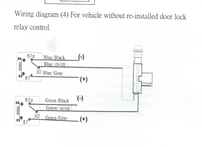
I have been trying to figure this lock/unlock harness to work with my aftermarket 2 wire actuator.  I looked at the info on this site and tried doing the reverse polarized relay hook up but didn't get it to work.  Here is what the diagram show's in the book, i can't figure this out...

Alarm Lock/Unlock wiring -- posted image.

Here is what the harness wires consist of:

Lock Wires:

Blue wire is Com. pin for terminal #30
Blue/gray wire is the N/O for terminal #87
Blue/black wire is the N/C for terminal #87a

Unlock Wires:

Green wire is Com. pin for terminal #30
GREEN/ gray wire is the N/O for terminal #87
GREEN/ black wire is the N/C for terminal #87a

This is all the info I got on how to hook this up...any help would be great!!!

chriswallace187 
Gold - Posts: 1,661
Gold spacespace
Joined: March 11, 2002
Location: Pennsylvania, United States
Posted: March 30, 2004 at 2:03 AM / IP Logged  
Are you trying to hook up a switch to control these actuators, or use them with an alarm/keyless entry unit, or both? If you're using an alarm, does it have positive or negative lock/unlock outputs?
That diagram is correct as far as what you need to hook 87, 87a, and 30 up to - just make sure both 87s are fused.
Terminals 85 and 86 on those relays will have varying hookup depending on what you're using to control the locks, but basically one side is going to be 12 volts and the other will be ground; and you can switch either one.
vang 
Member - Posts: 16
Member spacespace
Joined: December 29, 2003
Location: United States
Posted: April 01, 2004 at 11:40 PM / IP Logged  

chriswallace187 wrote:
Are you trying to hook up a switch to control these actuators, or use them with an alarm/keyless entry unit, or both? If you're using an alarm, does it have positive or negative lock/unlock outputs?
That diagram is correct as far as what you need to hook 87, 87a, and 30 up to - just make sure both 87s are fused.
Terminals 85 and 86 on those relays will have varying hookup depending on what you're using to control the locks, but basically one side is going to be 12 volts and the other will be ground; and you can switch either one.

I'm trying to hook it up to my keyless entry on my alarm...as far as I know, there is one more wire that is a Yellow/Blue wire that is used as a 2 step door unlock output, which has an output 300(-).   Do I have to hook this wire up somwhere also?

chriswallace187 
Gold - Posts: 1,661
Gold spacespace
Joined: March 11, 2002
Location: Pennsylvania, United States
Posted: April 02, 2004 at 6:57 PM / IP Logged  
You don't have to use the second unlock wire for anything - the main use for that is if you want to unlock the driver's door only with the first press of the button, and have a second press unlock the rest of the doors like factory keyless entry usually does.
vang 
Member - Posts: 16
Member spacespace
Joined: December 29, 2003
Location: United States
Posted: April 03, 2004 at 4:51 PM / IP Logged  

I'm still confused....

Here is where I'm confused...the blue and green wire that hooks to 30...

How does it run from the relay #30 to the actuator?

I ran my blue wire from the harness to the #30, but i got stumped on how to run that to the actuator too?  do i just run the blue wire to 30 and the actuator?  I'm kinda confused, I don't know if this makes any sense....

If you have any idea on which wire goes where, let me know...I've tried so many different ways with no luck...

Lock Wires:

Blue wire is Com. pin for terminal #30
Blue/gray wire is the N/O for terminal #87
Blue/black wire is the N/C for terminal #87a

Unlock Wires:

Green wire is Com. pin for terminal #30
GREEN/ gray wire is the N/O for terminal #87
GREEN/ black wire is the N/C for terminal #87a

chriswallace187 
Gold - Posts: 1,661
Gold spacespace
Joined: March 11, 2002
Location: Pennsylvania, United States
Posted: April 05, 2004 at 2:04 AM / IP Logged  
Read this:
https://www.the12volt.com/relays/relays.asp. It explains how relays work in general.
For this specific use, here's how your wires need to be hooked up.
The normally open terminals(GREEN/ gray and blue/gray in your lock relay wiring harness) need connected to constant fused 12v+.
The normally closed terminals(GREEN/ black and blue/black in the lock relay harness) need connected to ground.
The common terminals(green and blue in the lock relay harness) get connected to their respective wires going to the actuator. Don't connect these to anything but the actuator.
Terminals 86 on both relays get connected to constant fused 12v+.
Terminals 85 on the relays will go to the lock and unlock output wires from your alarm brain.

Sorry, you can NOT post a reply.
This topic is closed.

  Printable version Printable version Post ReplyPost New Topic
You cannot post new topics in this forum
You cannot reply to topics in this forum
You cannot delete your posts in this forum
You cannot edit your posts in this forum
You cannot create polls in this forum
You cannot vote in polls in this forum

  •  
Search the12volt.com
Follow the12volt.com Follow the12volt.com on Facebook
Wednesday, May 14, 2025 • Copyright © 1999-2025 the12volt.com, All Rights Reserved Privacy Policy & Use of Cookies
Disclaimer: *All information on this site ( the12volt.com ) is provided "as is" without any warranty of any kind, either expressed or implied, including but not limited to fitness for a particular use. Any user assumes the entire risk as to the accuracy and use of this information. Please verify all wire colors and diagrams before applying any information.

Secured by Sectigo
the12volt.com spacer
Support the12volt.com
Top
the12volt.com spacer