the12volt.com spacer
icon

97 F150 door lock


Post ReplyPost New Topic
< Prev Topic Next Topic >
bodine465 
Member - Posts: 2
Member spacespace
Joined: April 16, 2006
Location: United States
Posted: April 18, 2006 at 2:18 AM / IP Logged  

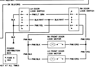
I've searched the forums and believe I've come up with the steps I'll have to take, but wanted to confirm it first. I'm trying to install a KCJS alarm with remote door lock into a 97 Ford F150 with power door locks, but without the factory security system or door remote. I understand that the F150 uses the bidirectional actuator and located this diagram, as well as the one from my service manual.

97 F150 door lock -- posted image. 

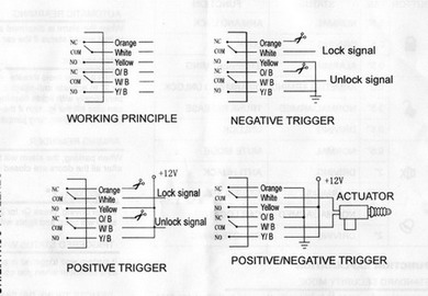
The alarm provides the following diagram, which I assumed I should use the 'positive/negative trigger' setup.

97 F150 door lock -- posted image.

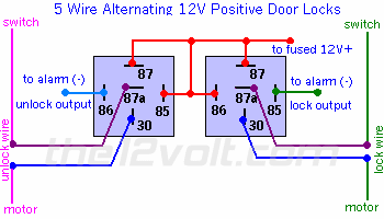
I've tried several different hookups on both switches, but only succeded in blowing a bunch of fuses. Tried both sides of the passenger's side switch. Nada... Is it possible to hook up the way it shows, which means I'm just screwing it up, or am I going to have to use this setup?

97 F150 door lock -- posted image.

One other thing. Is there a connector block accesible in the cab between the switches? Would prefer not to have to route wires throught the door.

Sorry about all the pics, but they should be worth...  let me count.... 4000 words.

Thanks in advance.

Bodine

Steven Kephart 
Platinum - Posts: 1,737
Platinum spaceThis member has been recognized as an authority in Mobile Audio and Video. Click here for more info.spaceThis member consistently provides reliable informationspace
Joined: November 06, 2003
Location: Oregon, United States
Posted: April 18, 2006 at 3:05 AM / IP Logged  
If you don't have factory keyless, then it is 5-wire and you want to wire it up like in your diagram.  You should be able to find the wires in the drivers kick pannel. 
Twelvoltz 
Platinum - Posts: 2,384
Platinum spaceThis member has made a donation to the12volt.com. Click here for more info.spaceThis member consistently provides reliable informationspace
Joined: March 24, 2005
Location: New Jersey, United States
Posted: April 18, 2006 at 7:41 AM / IP Logged  
Your truck's door lock motors rest at ground. This is why you are blowing fuses. Your diagram does not specifically list the 5 wire configuration that you need, it lists "adding actuators" but not the 5wire rest at ground. You are very close though. You would use the diagram that you found on this site here. But your system has internal relays and does not require the connections to pins 85 and 86 of the relays.
Your door lock wires are pink/black(lock) and RED / orange(unlock) located in the driver's kick panel so there is no need to go into the doors. You need to cut these wires and connect them like:
Orange (87a): Pink/Black (lock) cut wire to switch side
White (30): Pink/Black (lock) cut wire to motor side
Yellow (87): Constant fused +12V
ORANGE / Black (87a): RED / Orange (unlock) cut wire to switch side
WHITE/ Black (30): RED / Orange (unlock) cut wire to motor side
Yellow/Black (87): Constant fused +12V
Hope this helps.
Keep us posted.
mo12v 
Platinum - Nominee - Posts: 2,748
Platinum - Nominee spaceThis member consistently provides reliable informationspace
Joined: September 30, 2003
Location: Afghanistan
Posted: April 18, 2006 at 8:07 AM / IP Logged  

If your Alarm has the Instructions you Posted........Then your Alarm has ON Board Relays and you will NOT need additional Relays.

Find your LOCK & UNLOCK wires ( PINK / Yellow & PINK / Green ) Pass. Kick Panel
Cut them in Half.
One side of cut wires will have 12 Volts when you Press the DRIVER Door Switch.  ( this will be called Switch Side )
One side of cut wires  will show Nothing ( this will be called Motor Side )
5 Wire Reversal:
Lock:

ORANGE = Switch Side

WHITE = Motor Side
YELLOW = 12 Volts Constant

Unlock:

ORANGE / Black  = Switch Side

WHITE / Black = Motor Side
YELLOW/ Black  = 12 Volts Constant

MO
Don't Learn from Others Mistakes
You Might Be the One That Knows.
Twelvoltz 
Platinum - Posts: 2,384
Platinum spaceThis member has made a donation to the12volt.com. Click here for more info.spaceThis member consistently provides reliable informationspace
Joined: March 24, 2005
Location: New Jersey, United States
Posted: April 18, 2006 at 9:03 AM / IP Logged  
Hey Mo,
I read the manual this time 97 F150 door lock -- posted image.
LOL
mo12v 
Platinum - Nominee - Posts: 2,748
Platinum - Nominee spaceThis member consistently provides reliable informationspace
Joined: September 30, 2003
Location: Afghanistan
Posted: April 18, 2006 at 9:28 AM / IP Logged  
I am amazed at how much stuff can be posted.............
MO
Don't Learn from Others Mistakes
You Might Be the One That Knows.
Velocity Motors 
Moderator - Posts: 12,488
Moderator spaceThis member has made a donation to the12volt.com. Click here for more info.spaceThis member has been recognized as an authority in Electrical Theory. Click here for more info.spaceThis member has been recognized as an authority in Fabrication. Click here for more info.spaceThis member has been recognized as an authority in Mobile Audio and Video. Click here for more info.spaceThis member has been recognized as an authority in Mobile Security and Convenience. Click here for more info.spacespace
Joined: March 08, 2002
Location: Manitoba, Canada
Posted: April 18, 2006 at 9:57 AM / IP Logged  
Grab the wires at the driver's side HIGH up in the dash. It's virtually level with the instrument cluster on the truck. You will see a taped group of wires and you can find these wires there. If it's a 5 wire system, when you cut one of the two wire, you will loose functions for both lock and unlock at the switch.
Jeff
Velocity Custom Home Theater
Mobile Audio/Video Specialist
Morden, Manitoba CANADA
bodine465 
Member - Posts: 2
Member spacespace
Joined: April 16, 2006
Location: United States
Posted: April 18, 2006 at 8:46 PM / IP Logged  

You guys hit it right on the head. Pulled the driver's seat to make it easier to get under the dash and got her all hooked up. Screwed up by mixing up the lock wires with the unlock, but swapped the wires on the processor connector (didn't want to crawl back under the dash) and I was back in business. Looking into buying another and installing it in my 93 Ranger now.

Thanks again.

Jeff


Sorry, you can NOT post a reply.
This topic is closed.

  Printable version Printable version Post ReplyPost New Topic
You cannot post new topics in this forum
You cannot reply to topics in this forum
You cannot delete your posts in this forum
You cannot edit your posts in this forum
You cannot create polls in this forum
You cannot vote in polls in this forum

  •  
Search the12volt.com
Follow the12volt.com Follow the12volt.com on Facebook
Tuesday, May 6, 2025 • Copyright © 1999-2025 the12volt.com, All Rights Reserved Privacy Policy & Use of Cookies
Disclaimer: *All information on this site ( the12volt.com ) is provided "as is" without any warranty of any kind, either expressed or implied, including but not limited to fitness for a particular use. Any user assumes the entire risk as to the accuracy and use of this information. Please verify all wire colors and diagrams before applying any information.

Secured by Sectigo
the12volt.com spacer
Support the12volt.com
Top
the12volt.com spacer