the12volt.com spacer
icon

viper 211hv keyless entry kit


Post ReplyPost New Topic
< Prev Topic Next Topic >
wagonproject 
Member - Posts: 1
Member spacespace
Joined: October 21, 2007
Location: Michigan, United States
Posted: October 21, 2007 at 9:54 AM / IP Logged  
I recently got a Viper 211HV keyless entry kit and am trying to install it into my 1999 Chevy Blazer (4 door).
I've found this to be the general connection points I will need.
12volts red + ignition harness
Starter yellow + ignition harness
Ignition pink + ignition harness
Power Lock lt. blue + brown plug at BCM
Power Unlock white + brown plug at BCM
Parking Lights+ brown + lt. blue plug at BCM
Parking Lights- white - lt. blue plug at BCM
Trunk/Hatch Release black - purple plug at BCM
Horn Trigger black - steering column
And heres what I have as far as instructions
red     (+) 12v constant power input
blue    (-) 200mA second unlock output
BLACK/ white-1       input of domelight supervision relay #87
BLACK/ white         output of domelight supervision relay #30
GREEN/ black          lock #30 common output
WHITE/ black         lock #87 normally closed
violet/black          lock #87 normally open (input)
blue/black            unlock #30 common (output)
violet unlock #87 normally open (input)
white (+/-) parking light flash output
black   (-) chassis ground input
brown (-) horn honk output
lt. GREEN/ black     factory alarm disarm
WHITE/ blue         (-) 200 mA channel 3 validity output
yellow (+) switched ignition input (accessory)
orange (-) 500 mA ground-when-armed output
BROWN / black         unlock #87a normally closed
RED / white            (-) output of channel 2
I know I wont use a lot of those, or at least I dont think.
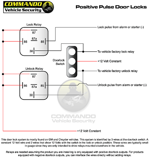
And then this pic I found.
viper 211hv keyless entry kit -- posted image.
Can someone help me make sense of this? I've done wiring before (For the air ride on my sierra and s10, but never anything like this. Any help is appreciated at pointing me in the right direction. Thank you.
KarTuneMan 
Platinum - Posts: 7,056
Platinum spaceThis member has made a donation to the12volt.com. Click here for more info.spaceThis member consistently provides reliable informationspace
Joined: December 14, 2004
Location: Isle Of Man
Posted: October 27, 2007 at 2:48 PM / IP Logged  
What is your "specific" question about?
sqall12001 
Member - Posts: 3
Member spacespace
Joined: July 03, 2007
Location: United States
Posted: October 30, 2007 at 9:38 AM / IP Logged  
It is changing the negative pulse from your alarm to a positive pulse to the door lock module, just take your time and follow the diagram. Shouldn't be too hard for you
-Nick
howie ll 
Pot Metal - Posts: 16,466
Pot Metal spacespace
Joined: January 09, 2007
Location: United Kingdom
Posted: October 30, 2007 at 10:09 AM / IP Logged  
You wont need extra relays, use the Viper wires as follows:- BROWN / Black and WHITE/ Black, discard, Purple and PURPLE / Black via 1amp fuse to 12v+ perm same source as your red cable.GREEN/ Black to lock and Blue/Black to unlock.
howie ll 
Pot Metal - Posts: 16,466
Pot Metal spacespace
Joined: January 09, 2007
Location: United Kingdom
Posted: October 30, 2007 at 10:15 AM / IP Logged  
PS I notice no mention of door contact dome light supervision if there is a green wire or purple wire on the Viper, join 1 side to ground other side to green, if not, one BLACK/ white to ground, other to drivers door contact.

Sorry, you can NOT post a reply.
This topic is closed.

  Printable version Printable version Post ReplyPost New Topic
You cannot post new topics in this forum
You cannot reply to topics in this forum
You cannot delete your posts in this forum
You cannot edit your posts in this forum
You cannot create polls in this forum
You cannot vote in polls in this forum

  •  
Search the12volt.com
Follow the12volt.com Follow the12volt.com on Facebook
Tuesday, May 13, 2025 • Copyright © 1999-2025 the12volt.com, All Rights Reserved Privacy Policy & Use of Cookies
Disclaimer: *All information on this site ( the12volt.com ) is provided "as is" without any warranty of any kind, either expressed or implied, including but not limited to fitness for a particular use. Any user assumes the entire risk as to the accuracy and use of this information. Please verify all wire colors and diagrams before applying any information.

Secured by Sectigo
the12volt.com spacer
Support the12volt.com
Top
the12volt.com spacer