the12volt.com spacer
icon

Wiring Relay for Fog Lights, Switch to 12 VDC


Post ReplyPost New Topic
< Prev Topic Next Topic >
jeeper-creeper 
Member - Posts: 7
Member spacespace
Joined: May 17, 2009
Location: Canada
Posted: May 17, 2009 at 8:29 PM / IP Logged  

Hi experts;

I don't know what the heck I'm doing, so hence me posting here.  I'm mechanically minded, but electrical boggles me (and scares me!). Wiring Relay for Fog Lights, Switch to 12 VDC -- posted image.

I have a set of 55W fog lights that are mounted on the rear bumper of my Jeep.  They used to be mounted on my Explorer and wired directly to the battery with an on/off switch when I uninstalled them (and I want to keep them wired directly to the battery to be able to operate without any need for ignition source). I took the wiring assembly apart intact (including a push button illuminated on/off switch) and was prepared to reinsatll them on the Jeep just as they were installed on the Explorer.  But when I took the lights and wiring to my local mechanic to see if they worked before I insalled them, he said worrds to the effect of "you don't need this, or that" and "I don't know why you have a relay", etc.  So off came the relay and some wiring and we did a test and sure enough, everything worked. "Great!" I thought! L"Less wiring to have to bugger with.

So back at home, I installed things exactly as I remembered the simple way thing were wired directly to the battery and sure enough, LIGHTS!  "Great!" I thought to myself once again and put everything away.  I used the lights a few times, no problems, but after a few uses, I turned the lights on and then couldn't get the push button on/off switch to depress to turn them off.  I finally got them turned off and disconnected the power wire from the battery until the morning.  In the morning, I took the back of the on/off switch off and saw that there had been some melting in the switch, thereby not allowing a proper "off" push.

So here's what I have:

A 14g (all are 14's) wire leading from the battery, through the firewall, open but not connected to anything. I have the spotlights connected at the rear bumper and grounded.  When I connect the wire from the spotlights to the wire connected to the battery, they get full brightness and power, so I know the lights are in working order.  As for "parts" that were disconnected from the working assembly of wires I had on the Explorer, I now have a three wire length of blue, yellow and green wires that were attached to the switch that melted.  I then have the 4 post relay (a HSIN DA 994-1A-12DM) that has 30, 85, 86 and 87 terminals. I have three wires leading from the relay to nothing and one is a definate ground, (judging by the end cap - round with a hole).  I've purchased a new LED toggle 3 post toggle switch (PICO part # 9413 511).

So being the electrical dummy that I am, how would someone recommend that I safely and properly connect everything so that I can have the lights turn on and off via the toggle switch?

Thanks in advance for your help.

P.S. - Someone's going to need to be quite the dummy proof writer so that I can clearly understand what's needed to do this correctly! ;)

Jarod
i am an idiot 
Platinum - Posts: 13,679
Platinum spaceThis member consistently provides reliable informationspace
Joined: September 21, 2006
Location: Louisiana, United States
Posted: May 17, 2009 at 8:38 PM / IP Logged  

How about a picture?  Would that be dummy proof enough.     Do you know which wire on the switch is the ground for the LED?  There is also a positive feed wire, do you know which wire that is?       Give me about 15 minutes for the picture.

jeeper-creeper 
Member - Posts: 7
Member spacespace
Joined: May 17, 2009
Location: Canada
Posted: May 17, 2009 at 8:44 PM / IP Logged  

Thanks for the prompt reply.  Yes I know which post is the ground on the switch as all three are labeled. "Supply Volts", "On Acc." and "Earth Ground".

As for the positive feed wire, this is why I posted in the forum section, as reading ingo like that in the Relay section just confuses me.  I warned you!  I'm an electrical idiot! Give me a transmission to rebuild, no problems.  But give me a light to turn on and I'll fry myself! ;)

Jarod
i am an idiot 
Platinum - Posts: 13,679
Platinum spaceThis member consistently provides reliable informationspace
Joined: September 21, 2006
Location: Louisiana, United States
Posted: May 17, 2009 at 8:49 PM / IP Logged  
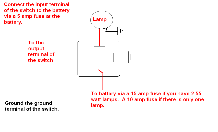
Wiring Relay for Fog Lights, Switch to 12 VDC -- posted image.
jeeper-creeper 
Member - Posts: 7
Member spacespace
Joined: May 17, 2009
Location: Canada
Posted: May 17, 2009 at 9:13 PM / IP Logged  

Ok...I think I understand where you're going with this, but let me put in my own lay-man's terms to be sure:

I connect one terminal of the relay directly to the wire that leads to the battery with a fuse, which I have - a 20 amp (bottom of relay diagram). 

I connect the relay to something grounded (right side of relay diagram). 

I connect the wire from the lights and ground the lights (top of relay diagram).

I connect the output terminal of the switch to the relay (left side of relay diagram).

That all makes sense, but looking at the diagram and reading what it says, I'm confused by four things;

1) - My switch has "Supply Volts", "On Acc." and "Earth Ground".  Which is the input and output terminal?  Grounding the switch is straight forward (thank goodness something is to me - for your sake!).

2) - I never had a 5 amp fuse connected when I had things wired in the Explorer and everything worked like a charm.  How necessary is this?

3) - It makes sense to have a wire leading from the switch to the battery, but when I had things connected in the Explorer, I only had one wire leading to the battery for power.  This diagram seems to indicate that I'll need two battery connections.  One for the relay and one for the switch.  is this correct?

4) - Which wires lead to the 30, 85, 86 and 87?  If this makes a huge difference, I don't want to mess it and fry everything.

Jarod
i am an idiot 
Platinum - Posts: 13,679
Platinum spaceThis member consistently provides reliable informationspace
Joined: September 21, 2006
Location: Louisiana, United States
Posted: May 17, 2009 at 9:34 PM / IP Logged  

1.  Supply Volts = Input terminal     On-Acc = Output terminal

2.  In a perfect world, not real necessary, but if something penetrates the insulation of the wire and it touches ground, a fire could be in order without a fuse.

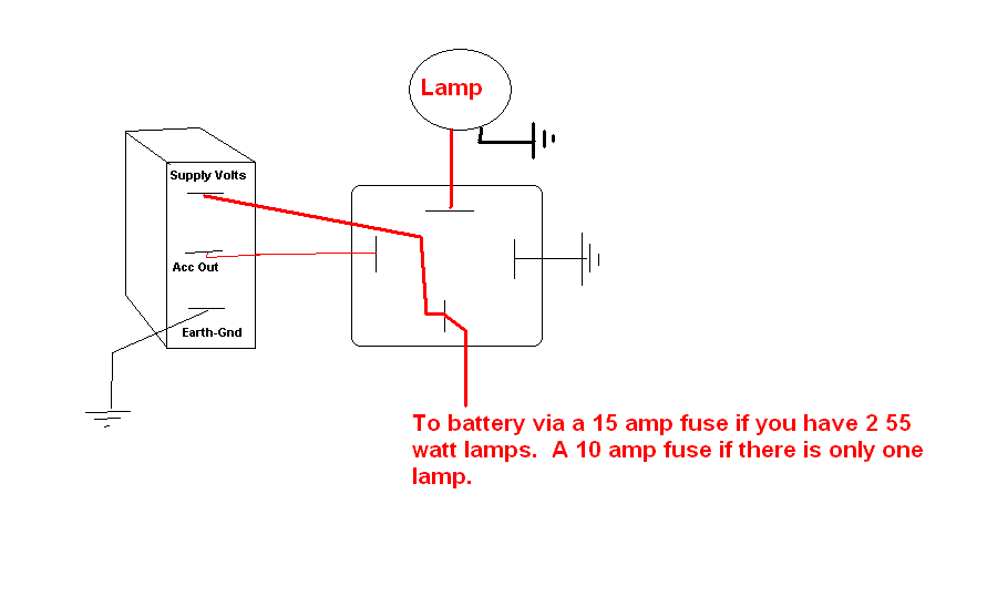
3.  You can connect the switch's power to the battery wire at the relay.  If it is a 14 Ga. wire the single fuse will be fine.  I did not know if the relay was going to be close to the switch.  If the wire to the switch is smaller in size than a 14 Ga, a smaller fuse to protect that wire may be in order.

4.  The picture is drawn so the pins of the relay are facing you.  85 is on the right.  30 at the bottom.

jeeper-creeper 
Member - Posts: 7
Member spacespace
Joined: May 17, 2009
Location: Canada
Posted: May 17, 2009 at 9:36 PM / IP Logged  

Just a quick side-note:

The green, yellow and blue wires that were connected to the switch are not in play in your diagram or explanation.  Just for interest sake, one end of the three have male connectors and the other end WAS connected directly to the 3 soldered bits of the inside of the switch.

Do I need this bit of wiring or is it obsolete with the way you've directed me to wire it?

Jarod
jeeper-creeper 
Member - Posts: 7
Member spacespace
Joined: May 17, 2009
Location: Canada
Posted: May 17, 2009 at 9:44 PM / IP Logged  

You mention proximity of the relay to the switch in your last posting. I'll have them both under the dashboard, but how close is too close?  If I want to wire things up with what is seemingly your easy way of doing it, what's best in this regard?  Opposite sides of the firewall or just a few inches (or more?) away from each other?

Thanks so much for your help so far!  I'm actually looking at things and able to see exactly what connects to what and minus a few proper male and female connectors, would have it done already!  Ta!

Jarod
i am an idiot 
Platinum - Posts: 13,679
Platinum spaceThis member consistently provides reliable informationspace
Joined: September 21, 2006
Location: Louisiana, United States
Posted: May 17, 2009 at 9:48 PM / IP Logged  

You can attach the relay to the switch if you like.  It makes no difference how close they are.  I had no idea if you were mounting the relay under the hood.  That is why I recommended running both to the battery.

Wiring Relay for Fog Lights, Switch to 12 VDC -- posted image.

jeeper-creeper 
Member - Posts: 7
Member spacespace
Joined: May 17, 2009
Location: Canada
Posted: May 17, 2009 at 9:50 PM / IP Logged  
Thank you!  It's getting a little late to be doing things tonight and I need to buy some news connectors before I do it, but I'll post a reply to let you know how it went and, I'm sure, to say thanks once again!
Jarod
Page of 2

  Printable version Printable version Post ReplyPost New Topic
You cannot post new topics in this forum
You cannot reply to topics in this forum
You cannot delete your posts in this forum
You cannot edit your posts in this forum
You cannot create polls in this forum
You cannot vote in polls in this forum

  •  
Search the12volt.com
Follow the12volt.com Follow the12volt.com on Facebook
Thursday, June 13, 2024 • Copyright © 1999-2024 the12volt.com, All Rights Reserved Privacy Policy & Use of Cookies
Disclaimer: *All information on this site ( the12volt.com ) is provided "as is" without any warranty of any kind, either expressed or implied, including but not limited to fitness for a particular use. Any user assumes the entire risk as to the accuracy and use of this information. Please verify all wire colors and diagrams before applying any information.

Secured by Sectigo
the12volt.com spacer
Support the12volt.com
Top
the12volt.com spacer