the12volt.com spacer
icon

12v timed reverse polarity circuit


Post ReplyPost New Topic
< Prev Topic Next Topic >
rballard 
Member - Posts: 4
Member spacespace
Joined: August 09, 2009
Location: Texas, United States
Posted: August 09, 2009 at 8:23 AM / IP Logged  

Wow, this forum is great. I've learned more about relays and circuits in last few days than in my entire life.

I've read quite a few posts on reverse polarity and relays but everything I can find uses a manually operated switch of one type or another to activate the circuit first one way and then the other. I need to have a timer in between the battery and the circuit so I don't have to be present to turn the power on. Let me explain my project.

I need to activate a door twice a day at preset times. I need the door to open in the morning and stay open all day, then close in the evening and stay closed all night. I have a 12v battery, a timer and a 12v motor that will open the door with polarity one way and close the door with reversed polarity. What I need is something that will reverse the polarity in the evening when the timer comes on to close the door. The timer has one positive wire and one negative wire so the voltage comes out of the timer the same way every time.

I hope I have explained it well enough. Can this polarity reversing thing be done with a relay instead of a manually operated switch? If so can someone please draw me a diagram showing how to wire it up. Thanks in advance for any help you can provide.

Thank You,
Russell Ballard
KPierson 
Platinum - Posts: 3,527
Platinum spaceThis member consistently provides reliable informationspace
Joined: April 14, 2005
Location: Ohio, United States
Posted: August 09, 2009 at 9:33 AM / IP Logged  
Will the door be damaged if voltage is constantly applied to the motor or does the door motor have internal limit switches to protect it?
Kevin Pierson
rballard 
Member - Posts: 4
Member spacespace
Joined: August 09, 2009
Location: Texas, United States
Posted: August 09, 2009 at 12:56 PM / IP Logged  

The motor does not have an internal limit switch. However it would be limited in run time by the timer. ie: Since it takes about 30 seconds for the door to open and/or close with the motor and set of gears I am using, the timer would turn the motor on everyday at 6:00am for only 30 seconds. Then the timer would turn it on again at 9:00pm every night for only 30 seconds.

It would kind of go like this:     Battery -----> Timer -----> Magic Black Box (Relay?) -----> Motor/Gear Module.

At 6:00am the timer passes current thru from the battery to the "Magic Black Box" for 30 seconds, which turns the motor clockwise for the 30 second period.

At 9:00pm the timer again passes current thru from the battery to the "Magic Black Box" for 30 seconds, but this time the "Magic Black Box" reverses the polarity and the motor turns counter clockwise for the 30 second period.

Any help would be much appreciated.

Thank You,
Russell Ballard
hotwaterwizard 
Silver - Posts: 1,350
Silver spacespace
Joined: December 11, 2003
Location: California, United States
Posted: August 12, 2009 at 11:49 PM / IP Logged  

A sprinkler timer and a couple of relays and a couple of off delay timers should do the trick.

I would suggest some kind of sensor like they have on garage doors just incase someone gets stuck in the door durring the process.

You could just buy all of the components but how much money do you want to spend?

It could cost you as much as $500

John DeRosa (Hotwaterwizard)
Stockton California
When in doubt, try it out !
hotwaterwizard 
Silver - Posts: 1,350
Silver spacespace
Joined: December 11, 2003
Location: California, United States
Posted: August 13, 2009 at 12:00 AM / IP Logged  

If you like I can try to figure out the circuit in my spare time. It may take a week or 2.

John DeRosa (Hotwaterwizard)
Stockton California
When in doubt, try it out !
hotwaterwizard 
Silver - Posts: 1,350
Silver spacespace
Joined: December 11, 2003
Location: California, United States
Posted: August 13, 2009 at 12:03 AM / IP Logged  
On second thought a Garage door opener would also do the job sensors and all then add the timers.
John DeRosa (Hotwaterwizard)
Stockton California
When in doubt, try it out !
rballard 
Member - Posts: 4
Member spacespace
Joined: August 09, 2009
Location: Texas, United States
Posted: August 13, 2009 at 9:14 PM / IP Logged  

I appreciate the answers. I am just electrically challenged I guess, because I can't figure it out. There are products on the market designed specifically for this purpose costing around $200. But I wanted to try to learn something and do it myself. Perhaps I should have picked an easier first project.

Thanks all,

Russell Ballard

Thank You,
Russell Ballard
i am an idiot 
Platinum - Posts: 13,674
Platinum spaceThis member consistently provides reliable informationspace
Joined: September 21, 2006
Location: Louisiana, United States
Posted: August 14, 2009 at 12:40 AM / IP Logged  

I have never used a DEI 528T.  But according to what I am reading here. https://www.the12volt.com/installbay/file.asp?ID=457  It appears as though you should be able to use 2 of these devices to achieve your goal.  If this will not work I hope that some of our hands on guys will let us know.  One unit with a cut loop, the other unit with loop intact.  Both units triggered via the same wire.  One unit connected to the close relay.  The other unit connected to the open relay.

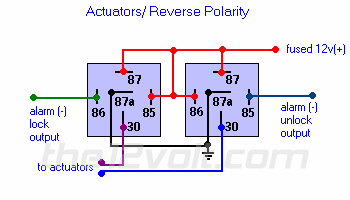
Actuators / Reverse Polarity
This is practically identical to the 5 wire alternating 12V(+) system above. The only difference is there's no switch! Both motor legs rest at ground at the relays. To lock or unlock the vehicle, polarity is changed on one motor leg.
 
12v timed reverse polarity circuit -- posted image.
 

One 528 output to wire labeled alarm lock output.  Other one to wire labeled alarm unlock output.

Wires labeled to actuators go to the motor that opens and closes door.

If this will not work, someone please let him know why it won't.

Let's Go Brandon Brown. Congratulations on your first Xfinity Series Win. LGBFJB
rballard 
Member - Posts: 4
Member spacespace
Joined: August 09, 2009
Location: Texas, United States
Posted: August 14, 2009 at 7:10 AM / IP Logged  

Would pins 85 and 86 be the positive and negative leads coming from my timer?

Russell

Thank You,
Russell Ballard
i am an idiot 
Platinum - Posts: 13,674
Platinum spaceThis member consistently provides reliable informationspace
Joined: September 21, 2006
Location: Louisiana, United States
Posted: August 14, 2009 at 10:38 AM / IP Logged  
Your timer would connect to the 528Ts.  The output from one will connect to 85 of one relay and the ouput from the other 528 will connect to 86 of the second relay.
Let's Go Brandon Brown. Congratulations on your first Xfinity Series Win. LGBFJB

Sorry, you can NOT post a reply.
This topic is closed.

  Printable version Printable version Post ReplyPost New Topic
You cannot post new topics in this forum
You cannot reply to topics in this forum
You cannot delete your posts in this forum
You cannot edit your posts in this forum
You cannot create polls in this forum
You cannot vote in polls in this forum

  •  
Search the12volt.com
Follow the12volt.com Follow the12volt.com on Facebook
Thursday, May 23, 2024 • Copyright © 1999-2024 the12volt.com, All Rights Reserved Privacy Policy & Use of Cookies
Disclaimer: *All information on this site ( the12volt.com ) is provided "as is" without any warranty of any kind, either expressed or implied, including but not limited to fitness for a particular use. Any user assumes the entire risk as to the accuracy and use of this information. Please verify all wire colors and diagrams before applying any information.

Secured by Sectigo
the12volt.com spacer
Support the12volt.com
Top
the12volt.com spacer