the12volt.com spacer
icon

relay, coolant level sensor


Post ReplyPost New Topic
< Prev Topic Next Topic >
dr_harika 
Member - Posts: 8
Member spacespace
Joined: April 19, 2007
Location: Australia
Posted: September 20, 2009 at 7:03 AM / IP Logged  
Hi guys,
My dilema is trying to make a coolant level sensor work in my car (not equipped with one from factory) using a relay (or perhaps something else?).
I have installed a Coolant Level Sensor, and it has two resistances (nothing inbetween).
180ohm when there is coolant present
1450ohm when the coolant is low.
My intention was to somehow use the difference in resistance to activate a relay coil, so that it turns on a 12v light i will install on the dash.... I have been trying to connect one side of the relay coil to 12v ACC, and the other side of the coil to the coolant sensor and then ground; but once the relay activates, it stays activated until power is removed.
Any help or ideas is appreciated.
Thanks.
dr_harika.
KPierson 
Platinum - Posts: 3,527
Platinum spaceThis member consistently provides reliable informationspace
Joined: April 14, 2005
Location: Ohio, United States
Posted: September 20, 2009 at 9:45 AM / IP Logged  

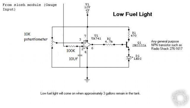
There is a post on here somewhere from "I am an idiot" that shows how to make a low fuel light based on a change in resistance (it's an op amp circuit). 

You can use the coolant switch as one half of a voltage divider and then use the voltage divider output to feed an op amp.  The output of the opamp can drive a transistor that drives a relay.

Kevin Pierson
howie ll 
Pot Metal - Posts: 16,466
Pot Metal spacespace
Joined: January 09, 2007
Location: United Kingdom
Posted: September 20, 2009 at 10:23 AM / IP Logged  
Probably cheaper to buy and simpler to install an aftermarket temp. gauge, I'd feel safer with one of those than a warning light.
dr_harika 
Member - Posts: 8
Member spacespace
Joined: April 19, 2007
Location: Australia
Posted: September 21, 2009 at 6:58 AM / IP Logged  
thanks for the idea. will need to look into it.
I couldn't find "i am an idiot"'s post or any that were relevant. He has 6000+ posts, so was hard to filter.
Could my idea work with a PIC microchip with some sort of analogue input? and an output to drive a relay?
I have a PIC programmer and know the basics (but only have delt with digital inputs)
Any help is greatly appreciated.
KPierson 
Platinum - Posts: 3,527
Platinum spaceThis member consistently provides reliable informationspace
Joined: April 14, 2005
Location: Ohio, United States
Posted: September 21, 2009 at 7:26 AM / IP Logged  

Using a microcontroller would greatly simplify things.

It's the same basic outline though, add a resistor to create a voltage divider and then feed that voltage in to an analog input.  I'm not a PIC guy, so I can't give you specific details on the best route to go after that.  Ideally, you'll have only an 8 bit ADC to make all the calculations "easy".  If you have more then an 8 bit ADC shift out the LSBs to leave you with only the 8 MSBs.  After that, especially with your application, it's pretty easy since you will always only have one voltage or the other.  In fact, if you calculated the voltage that is directly in the middle of the two possible voltages you would only need one comparison.

You will still need the transistor and diode on the output of the PIC to drive a relay, and you'll still need a base resistor.

Kevin Pierson
dr_harika 
Member - Posts: 8
Member spacespace
Joined: April 19, 2007
Location: Australia
Posted: September 26, 2009 at 9:21 PM / IP Logged  
Thanks for the help gents,
I solved the problem by using an OP amp (LM741).
I connected the inverting input (pin 2) to the top of a 5.1v zener diode which is limited by a 510ohm resistor.. 5.1v is the reference voltage for the basis of my voltage divider.
The non-inverting input (pin 3) was connected to the voltage divider made from the coolant sensor (connecting to ground), and the other side was a 430 ohm resistor connecting to ACC 12v+.
As for the output, it put a 510ohm resistor, and a 3.3v LED, and placed it in the dash.
works a treat. it is triggered just below the "low" level on the coolant bottle.
thanks for the help.. with this concept, i can now do my auto lights (with a light sensor).. never really knew how to use it.
I also want to learn how to use PIC's for anything other than basic switch circuits.
light
hotwaterwizard 
Silver - Posts: 1,350
Silver spacespace
Joined: December 11, 2003
Location: California, United States
Posted: October 10, 2009 at 2:37 PM / IP Logged  
relay, coolant level sensor -- posted image.
John DeRosa (Hotwaterwizard)
Stockton California
When in doubt, try it out !
ckeeler 
Gold - Posts: 1,461
Gold spacespace
Joined: June 20, 2008
Location: New Mexico, United States
Posted: October 12, 2009 at 12:32 PM / IP Logged  

i actually saved that schematic you are talking about KP. here it is

relay, coolant level sensor -- posted image.


Sorry, you can NOT post a reply.
This topic is closed.

  Printable version Printable version Post ReplyPost New Topic
You cannot post new topics in this forum
You cannot reply to topics in this forum
You cannot delete your posts in this forum
You cannot edit your posts in this forum
You cannot create polls in this forum
You cannot vote in polls in this forum

  •  
Search the12volt.com
Follow the12volt.com Follow the12volt.com on Facebook
Friday, May 16, 2025 • Copyright © 1999-2025 the12volt.com, All Rights Reserved Privacy Policy & Use of Cookies
Disclaimer: *All information on this site ( the12volt.com ) is provided "as is" without any warranty of any kind, either expressed or implied, including but not limited to fitness for a particular use. Any user assumes the entire risk as to the accuracy and use of this information. Please verify all wire colors and diagrams before applying any information.

Secured by Sectigo
the12volt.com spacer
Support the12volt.com
Top
the12volt.com spacer