the12volt.com spacer
icon

is this 3 relay diagram correct?


Post ReplyPost New Topic
< Prev Topic Next Topic >
linkinpark3223 
Member - Posts: 4
Member spacespace
Joined: December 28, 2009
Location: Indiana, United States
Posted: January 01, 2010 at 7:09 AM / IP Logged  
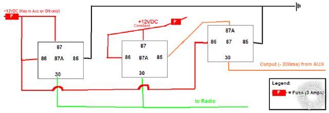
Hello, I had a quick diagram that I came up with that I wanted to make sure was ok. All three relays in the Picture are SPDT.
First things first, this is for powering a radio (not a car radio) in the car. The radio needs a max power of 3 amps +12VDC to operate. Right now, it is a one wire 3 amp fused installation. The wire only becomes hot when the key is in the ACCESSORY or ON position (tapped off of windshield wipers in fuse box). I also want the wire to become hot when my remote start (not installed yet) sends a 200ma negative signal out of one of its AUX outputs. There is a possibility that they could both be on, so I obviously do not want that.
The picture should work right? The relay on the left is for triggering the powering on of the radio when the key is in ACC or ON. The middle one is for the Remote Start AUX trigger. And the right one prevents them from both being on. If both are set to on, only the far left relay will power the radio and not the middle one, since the far left relay energizes the far right relay which breaks the connection of the middle relay.
So really, I just want to know if this will work how I want it to work. I went over it a few times and it seems to work. And if you look at it and see if it does work, is there an easier way to do this? I guess the other way would be to eliminate the last relay, and use 3 amp diodes on the two green wires from each relay that go to the radio. Just wondering if this is right and what my alternatives are.
Sorry about the crappy drawing.
Thanks for the future replies!
is this 3 relay diagram correct? -- posted image.
i am an idiot 
Platinum - Posts: 13,714
Platinum spaceThis member consistently provides reliable informationspace
Joined: September 21, 2006
Location: Louisiana, United States
Posted: January 01, 2010 at 7:20 AM / IP Logged  

Is your goal to be able to turn the radio on when the vehicle is not under a remote start episode?

linkinpark3223 
Member - Posts: 4
Member spacespace
Joined: December 28, 2009
Location: Indiana, United States
Posted: January 01, 2010 at 7:32 AM / IP Logged  
i am an idiot wrote:

Is your goal to be able to turn the radio on when the vehicle is not under a remote start episode?

Yes, I want the radio to turn on when the Key is in ACC or RUN (first relay) or when the remote start is outputting a 200ma negative on that AUX line (second relay) that can be activated as a "Latch" output via the remote . And the reason for the AUX is because, yes, I want the radio to be able to be turned on without the vehicle in a remote start episode (which would power the RUN line anyways and turn the radio on as it is now).
KPierson 
Platinum - Posts: 3,527
Platinum spaceThis member consistently provides reliable informationspace
Joined: April 14, 2005
Location: Ohio, United States
Posted: January 01, 2010 at 9:04 AM / IP Logged  

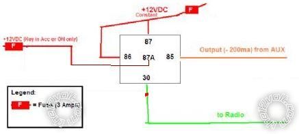
What about something like this?  Same basic concept, but only one relay

is this 3 relay diagram correct? -- posted image.

This puts the "priority" on the (-) output but I don't see how that could be a bad thing.

Kevin Pierson
linkinpark3223 
Member - Posts: 4
Member spacespace
Joined: December 28, 2009
Location: Indiana, United States
Posted: January 01, 2010 at 9:32 AM / IP Logged  
KPierson wrote:

What about something like this?  Same basic concept, but only one relay

is this 3 relay diagram correct? -- posted image.

This puts the "priority" on the (-) output but I don't see how that could be a bad thing.

Heh, guess I was thinking to deep lol. Ya, that would work just fine for me. Doesn't matter on the priority really. That one relay will do what I want. Thanks, I knew their had to be a simpler way, but when I originally thought about it, my mind thought of two relays, but I guess if I thought about just one, that might have came to my mind lol.
Thanks! is this 3 relay diagram correct? -- posted image.
howie ll 
Pot Metal - Posts: 16,466
Pot Metal spacespace
Joined: January 09, 2007
Location: United Kingdom
Posted: January 02, 2010 at 9:36 AM / IP Logged  
Or how about the fact that most decent remote starts have an ACC or 2nd IGN output and since it's only 3amp, draw off an existing ACC and no relays required! KISS!
linkinpark3223 
Member - Posts: 4
Member spacespace
Joined: December 28, 2009
Location: Indiana, United States
Posted: January 02, 2010 at 2:35 PM / IP Logged  
howie ll wrote:
Or how about the fact that most decent remote starts have an ACC or 2nd IGN output and since it's only 3amp, draw off an existing ACC and no relays required! KISS!
Ya, but then the radio would only activate during remote start. The way it is hooked up now (tapped off of windshield wipers) the remote start would already turn it on. I also want the ability to turn it on WITHOUT remote starting the car. The Remote start has 2 AUX outputs that are negative that can be turned on and off from the remote, regardless if your car is started or not. That's why I need the relay.
howie ll 
Pot Metal - Posts: 16,466
Pot Metal spacespace
Joined: January 09, 2007
Location: United Kingdom
Posted: January 02, 2010 at 5:46 PM / IP Logged  
OK linkin, go with K Pierson's 'cause that's correct.

Sorry, you can NOT post a reply.
This topic is closed.

  Printable version Printable version Post ReplyPost New Topic
You cannot post new topics in this forum
You cannot reply to topics in this forum
You cannot delete your posts in this forum
You cannot edit your posts in this forum
You cannot create polls in this forum
You cannot vote in polls in this forum

  •  
Search the12volt.com
Follow the12volt.com Follow the12volt.com on Facebook
Monday, June 30, 2025 • Copyright © 1999-2025 the12volt.com, All Rights Reserved Privacy Policy & Use of Cookies
Disclaimer: *All information on this site ( the12volt.com ) is provided "as is" without any warranty of any kind, either expressed or implied, including but not limited to fitness for a particular use. Any user assumes the entire risk as to the accuracy and use of this information. Please verify all wire colors and diagrams before applying any information.

Secured by Sectigo
the12volt.com spacer
Support the12volt.com
Top
the12volt.com spacer