the12volt.com spacer
icon

aux lights relay diagram.


Post ReplyPost New Topic
< Prev Topic Next Topic >
pfbz 
Member - Posts: 5
Member spacespace
Joined: April 25, 2011
Location: Colorado, United States
Posted: December 04, 2011 at 10:29 PM / IP Logged  
I want to wire up some aux lights, and it's a little different than I've done things in the past.
I'd like three modes with a single double throw center off switch.
- Aux lights off. (center)
- Aux lights on (up, ignition on).
- Aux lights on (down,high beams).
Typically, I'd wire the positive side through a switch and to the relay trigger. But in this case, since the switched 12v and headlight 12v are already in the engine compartment, near the relays, near the lights, it seems it might be easier to switch the ground instead, which I've never done before. Does this circuit look like it will work for my purposes?
http://paulor.smugmug.com/Image-Hosting-1/Forums/web/i-QXbw2g4/0/M/relay-diagram-M.jpg
aux lights relay diagram. -- posted image.
pfbz 
Member - Posts: 5
Member spacespace
Joined: April 25, 2011
Location: Colorado, United States
Posted: December 04, 2011 at 10:31 PM / IP Logged  
Hmmm... Guess I can't edit my post. That should be Double PULL switch, not Double throw.
howie ll 
Pot Metal - Posts: 16,466
Pot Metal spacespace
Joined: January 09, 2007
Location: United Kingdom
Posted: December 05, 2011 at 2:35 AM / IP Logged  
Quite correct though two things spring to mind.
You show an SPCO (single pole changeover) switch in the diagram but from what you wrote after I'm sure you're aware.
Second I hope your high beams only come on with the ignition, otherwise that could leave you with high beams and aux lights permanently on unless you remember to turn off that switch (or run the ground side through an ignition controlled relay).
oldspark 
Gold - Posts: 4,913
Gold spacespace
Joined: November 03, 2008
Location: Australia
Posted: December 05, 2011 at 12:47 PM / IP Logged  
And unless the 87a's go to something different, you could use a single relay and feed the hibeam & +12V switched through diodes.
That's just to save a relay and space at the expense of 2 diodes.
But I might use the 2 relays as shown for redundancy - ie, no need to carry a spare relay, the spare is in use and can be swapped upon failure if needed, else the other circuit used and relay replaced whenever convenient.
[ Redundancy can be academic - the difference in reliability between 2 diodes and 1 relay as opposed to 2 relays may be insignificant - or maybe the 2 diodes and relay are more reliable. The question is, when the sole relay fails (hence no aux lights), is it acceptable (until it can be fixed)? Or is it better to be able to use "half" the circuit (with the still-working relay)? ]
pfbz 
Member - Posts: 5
Member spacespace
Joined: April 25, 2011
Location: Colorado, United States
Posted: December 05, 2011 at 8:50 PM / IP Logged  
howie ll wrote:
...you show an SPCO (single pole changeover) switch in the diagram ...
Second I hope your high beams only come on with the ignition, otherwise that could leave you with high beams and aux lights permanently on unless you remember to turn off that switch
Yes, the headlights (hi or low) turn off with the ignition, after an adjustable exit delay. On the diagram, I tried using OmniGraffle for the first time. Gave up trying to find a good relay template, so I built my own, but grabbed a switch diagram from their templates... Should have made that one too!
oldspark wrote:
...and unless the 87a's go to something different, you could use a single relay and feed the hibeam & +12V switched through diodes.
Not following how to do this... If I feed both the switched 12V and high beams through diodes into 86, then I would loose my 'switched with high beam' functionality. 87a would be an inverted output, not sure how that would help, but I'm not an expert on relays, which is why I posted here!
oldspark 
Gold - Posts: 4,913
Gold spacespace
Joined: November 03, 2008
Location: Australia
Posted: December 06, 2011 at 1:30 AM / IP Logged  
Yes you are right. I overlooked the DPST switch... aux lights relay diagram. -- posted image.
Ignore my entire last reply.
(Except for the bit about me preferring the 2 relays anyhow, ie, iac pfbz's diagram...)
pfbz wrote:
I'm not an expert on relays, ...!
Yeah, right.... aux lights relay diagram. -- posted image.
You nailed their logic. (And me to a cross!)
howie ll 
Pot Metal - Posts: 16,466
Pot Metal spacespace
Joined: January 09, 2007
Location: United Kingdom
Posted: December 06, 2011 at 1:38 AM / IP Logged  
Who needs to be an expert? They are either switches or changeover switches, functions to increase current, change current flow or polarity reversal.
As basic units.
oldspark 
Gold - Posts: 4,913
Gold spacespace
Joined: November 03, 2008
Location: Australia
Posted: December 06, 2011 at 2:06 AM / IP Logged  
A practiced Expert? Not if self-taught or tutored sufficiently - at least the logic part.
But Howie, the question is, "can an expert be wrong"?
Alas, it's past my bed time.
Goodnight.
howie ll 
Pot Metal - Posts: 16,466
Pot Metal spacespace
Joined: January 09, 2007
Location: United Kingdom
Posted: December 06, 2011 at 2:11 AM / IP Logged  
Of course we can.
Go back to burying the FB111s in that field.
infernicus 
Member - Posts: 1
Member spacespace
Joined: December 11, 2009
Location: New York, United States
Posted: December 17, 2011 at 12:17 AM / IP Logged  
I believe this may help..
This is how to set up a three (3) position switch.
One is to have the lights come on automatically when triggered by another power source, ie: reverse lights/parking lights.
Two is off all the time
Three is turn them on independently.
On the Switch
    -One side goes to fused ignition power (on the diagram it is written for constant power, not ignition switched.)
    -Middle goes to trigger post 86 on relay
    -Other side goes to what you want to tap into (ie: reverse lights)
On the Relay
    -30 goes to fused 12v power
    -86 goes to middle terminal on switch
    -85 goes to a ground
    -87 goes to Aux Lights
This is the correct Diagram to use with the wires going to where I just mentioned.
aux lights relay diagram. -- posted image.
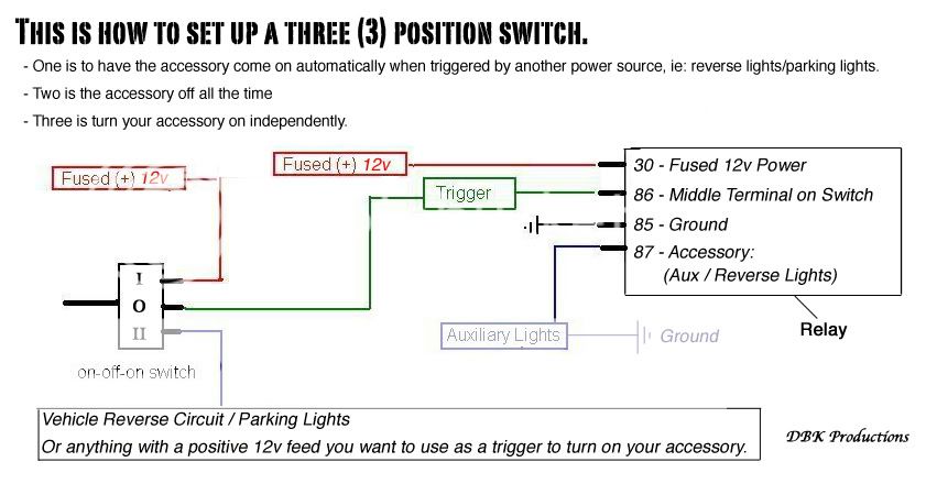
These are the switches I used.
http://www.allelectronics.com/make-a-store/item/RS-146/SPDT-CENTER-OFF-ROUND-ROCKER-SWITCH/1.html
Page of 2

  Printable version Printable version Post ReplyPost New Topic
You cannot post new topics in this forum
You cannot reply to topics in this forum
You cannot delete your posts in this forum
You cannot edit your posts in this forum
You cannot create polls in this forum
You cannot vote in polls in this forum

  •  
Search the12volt.com
Follow the12volt.com Follow the12volt.com on Facebook
Wednesday, May 14, 2025 • Copyright © 1999-2025 the12volt.com, All Rights Reserved Privacy Policy & Use of Cookies
Disclaimer: *All information on this site ( the12volt.com ) is provided "as is" without any warranty of any kind, either expressed or implied, including but not limited to fitness for a particular use. Any user assumes the entire risk as to the accuracy and use of this information. Please verify all wire colors and diagrams before applying any information.

Secured by Sectigo
the12volt.com spacer
Support the12volt.com
Top
the12volt.com spacer