


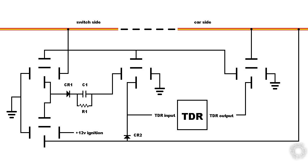
 It works in my head, but it's untested. Maybe you can proofread it for me. You'll cut the headlight wire behind the switch (which I believe is red/yellow). R1 is a bleed resistor, 1K ohms or higher. You may need to try different values for C1. CR1/CR2 are standard switching diodes.
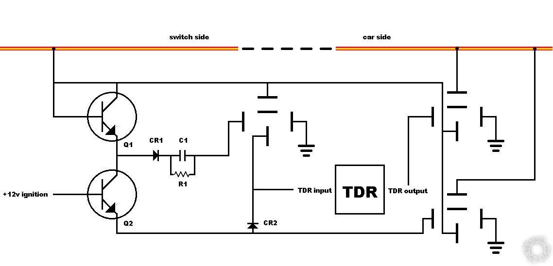 This will eliminate the excess current draw of the initial diagram.
 Printable version


| You cannot post new topics in this forum You cannot reply to topics in this forum You cannot delete your posts in this forum You cannot edit your posts in this forum You cannot create polls in this forum You cannot vote in polls in this forum |

| Search the12volt.com |
Follow the12volt.com 
Thursday, April 30, 2026 • Copyright © 1999-2026 the12volt.com, All Rights Reserved • Privacy Policy & Use of Cookies

Thursday, April 30, 2026 • Copyright © 1999-2026 the12volt.com, All Rights Reserved • Privacy Policy & Use of Cookies
Disclaimer:
*All information on this site ( the12volt.com ) is provided "as is" without any warranty of any kind, either expressed or implied, including but not limited to fitness for a particular use. Any user assumes the entire risk as to the accuracy and use of this information. Please
verify all wire colors and diagrams before applying any information.
