the12volt.com spacer
icon

current sensing relay?


Post ReplyPost New Topic
< Prev Topic Next Topic >
jrmedved 
Member - Posts: 1
Member spacespace
Joined: October 19, 2007
Location: Nevada, United States
Posted: October 19, 2007 at 12:27 AM / IP Logged  

I found this site through a google search.  I am hoping that someone here may view this post and be able to offer some guidance?

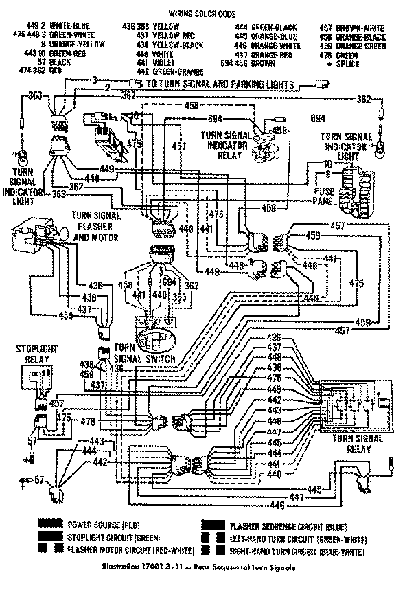
I am trying to find some kind of current sensing relay that is adjustable.  My dilemma is that I have a 1967 Ford Thunderbird.  The car was designed with a sequential turn signal system.  Part of the circuit is a relay located under the dashboard which opens when the current draw reaches a certain point and closes when it falls off again.  This open and closing of the relay flashes the dashboard turn signal indicators.  The way that the relay is supposed to work is that the turn signal system lights the front and rear turn signal bulbs, and then adds the center rear bulb, and then finally the third.  Once all bulbs are lighted, the current draw is supposed to trip the relay to open, thus turning off the dash indicator momentarily.  When the flasher motor has turned off all bulbs, the relay closes, thus lighting the dash indicator, and then the cycle repeats.

The problem is that as these cars age, some portion of the current draw is lost and not enough current flows through the (original) relay to trigger it to open the circuit.  Thus, the dash indicators never flash off, they dim progressively as there is more draw from the battery.  This problem is prevelant is nearly all 60's Thunderbirds with sequential flashers. 

So, what i am trying to locate is a similar relay but with an adjustment control to it that I can decrease the amount of voltage that has to flow through the relay to open its circuit. 

Any ideas would be great.  If you need further information I will do my best to provide it to get to a solution.

Jeff Medved
Las Vegas, Nevada
dualsport 
Silver - Posts: 983
Silver spacespace
Joined: September 27, 2005
Location: United States
Posted: October 20, 2007 at 12:44 AM / IP Logged  
Sounds like you could put together an electronic circuit using a voltage comparator and relay driver to do it.
With a low sensing resistance in line with the lighting power and the normally closed contacts of the turn signal relay, it could be set up so that it would turn on when the voltage across the current sense resistor goes above your threshold point (when all three lights come on).
Once it toggles, the output goes to a transistor driver for the relay. Probably want to add a small delay after it trips, so the third lamp stays on for a bit instead of immediately turning back off. The relay energizes at that point, switching the contact paths.
The relay would open up the connection path and turn the lights off, and the current through the sense resistor drops back down to zero, turning off the comparator again. Rinse and repeat.
i am an idiot 
Platinum - Posts: 13,693
Platinum spaceThis member consistently provides reliable informationspace
Joined: September 21, 2006
Location: Louisiana, United States
Posted: October 20, 2007 at 8:01 AM / IP Logged  

Is the indicator the only problem?   If so you could run wires from the middle bulb to the indicator or the outer bulb for that matter.  Depending on how long you want the indicator to stay lit.   Unless of course they are single element bulbs that double as taillights.

hotwaterwizard 
Silver - Posts: 1,350
Silver spacespace
Joined: December 11, 2003
Location: California, United States
Posted: October 24, 2007 at 9:12 AM / IP Logged  
current sensing relay? -- posted image.
John DeRosa (Hotwaterwizard)
Stockton California
When in doubt, try it out !
KPierson 
Platinum - Posts: 3,527
Platinum spaceThis member consistently provides reliable informationspace
Joined: April 14, 2005
Location: Ohio, United States
Posted: October 24, 2007 at 1:58 PM / IP Logged  

Could you possibly use a bimetallic turn signal switch from a current generation vehicle as a starting point?  They work on the same principal - load it up with current until the circuit opens.  You would then need a few components to make it work correctly, but it would be a cheap starting point.

Kevin Pierson
hotwaterwizard 
Silver - Posts: 1,350
Silver spacespace
Joined: December 11, 2003
Location: California, United States
Posted: October 25, 2007 at 12:56 AM / IP Logged  

Nice solution.

A blinker bulb from a Christmas light string would have a more sensitive current rating.

Most of them are 12v bulbs as well.

John DeRosa (Hotwaterwizard)
Stockton California
When in doubt, try it out !

Sorry, you can NOT post a reply.
This topic is closed.

  Printable version Printable version Post ReplyPost New Topic
You cannot post new topics in this forum
You cannot reply to topics in this forum
You cannot delete your posts in this forum
You cannot edit your posts in this forum
You cannot create polls in this forum
You cannot vote in polls in this forum

  •  
Search the12volt.com
Follow the12volt.com Follow the12volt.com on Facebook
Thursday, October 31, 2024 • Copyright © 1999-2024 the12volt.com, All Rights Reserved Privacy Policy & Use of Cookies
Disclaimer: *All information on this site ( the12volt.com ) is provided "as is" without any warranty of any kind, either expressed or implied, including but not limited to fitness for a particular use. Any user assumes the entire risk as to the accuracy and use of this information. Please verify all wire colors and diagrams before applying any information.

Secured by Sectigo
the12volt.com spacer
Support the12volt.com
Top
the12volt.com spacer