the12volt.com spacer
icon

DPDT Switch to Activate Backup Camera?


Post ReplyPost New Topic
< Prev Topic Next Topic >
la mouche 
Member - Posts: 5
Member spacespace
Joined: January 28, 2009
Location: Ontario, Canada
Posted: January 28, 2009 at 8:52 PM / IP Logged  

I am new at this. I plan on installing a backup camera on my 2005 Ford F150. I wish to connect it two ways using a dpdt switch. The switch in "Up" would be "auto", to turn on automatically when putting vehicle in reverse, pushing the switch "down" would be steady on. Can anyone help me wiring this thing to work correctly?

Also, should I use a spdt switch or a dpdt switch?

thank you

KPierson 
Platinum - Posts: 3,527
Platinum spaceThis member consistently provides reliable informationspace
Joined: April 14, 2005
Location: Ohio, United States
Posted: January 28, 2009 at 9:00 PM / IP Logged  

You could use either, but a SPDT would be the easiest (less pins to worry about).

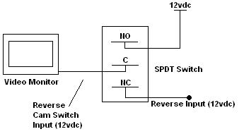
Wire the "common" pin of the switch to a 12vdc switch input (the input on your video screen that switches to the reverse camara when it gets a signal). 

Wire one of the contacts (NC say for the auto part) to the 12vdc reverse signal of the car - this is the signal that turns the reverse lights on on the back of the vehicle.

Wire the remaining contact of the switch (NO) to constant 12vdc.

This assumes your switch input is +12vdc.  If it needs a ground to switch you will need to add a relay to change the polarity.

Kevin Pierson
KPierson 
Platinum - Posts: 3,527
Platinum spaceThis member consistently provides reliable informationspace
Joined: April 14, 2005
Location: Ohio, United States
Posted: January 28, 2009 at 9:04 PM / IP Logged  

DPDT Switch to Activate Backup Camera? -- posted image.

Here is a little picture.

Kevin Pierson
i am an idiot 
Platinum - Posts: 13,714
Platinum spaceThis member consistently provides reliable informationspace
Joined: September 21, 2006
Location: Louisiana, United States
Posted: January 28, 2009 at 9:29 PM / IP Logged  
The camera would have to be fed power from a source other than the reverse wire.  Or it would have to be diode isolated to prevent the reverse lights from coming on when you have it switched on via your switch.  I think a DPDT switch might be necessary to power the camera and switch the deck.  Or the camera could be powered via an ignition power source, however I have no idea if this will shorten the camera's life expectancy or not.  I would power it only when in use.  I will draw a diagram and post it later.
KPierson 
Platinum - Posts: 3,527
Platinum spaceThis member consistently provides reliable informationspace
Joined: April 14, 2005
Location: Ohio, United States
Posted: January 28, 2009 at 9:44 PM / IP Logged  

To power the camera I would use a relay off the reverse signal.  Depending on the camera the relay may not be necesarry, but I would use one just to be safe:

Pin 85 - ground

Pin 86 - reverse signal (12vdc)
Pin 30 - fused 12vdc power
Pin 87 - camera output

I've never installed a rear camera system but I took a look at a service manual for a 2008 Infiniti G37.  They, from the factory, switch the camera on only when the car is in reverse (and they use a 6 vdc signal to do it).  I would guess there would be a very good reason for this and you most likely hit it on the head - service life of the camera.

If your camera uses very little current (under 500mA) you could technically tie it in the Common pin of the circuit I drew above.  The switch would provide isolation and you wouldn't have to worry about backfeeding the reverse lights.

Kevin Pierson
la mouche 
Member - Posts: 5
Member spacespace
Joined: January 28, 2009
Location: Ontario, Canada
Posted: January 28, 2009 at 11:15 PM / IP Logged  

if I go with the spdt switch as illustrated above, you indicate that the common (middle wire) to be connected to the reverse cam switch input (which I do not have, I have a regular monitor with RCA input), you also indicate that the "Normally Closed" circuit be connected to 12v + reverse input and the "Normally Open" to a constant 12v + source (ignition). This question might sound stupid, but where am I suppose to connect the wire that goes to the camera itself?

Maybe I wasn't clear on what I plan to do. I want to install a switch to be able to select to either use the camera automatically when I put the truck in reverse, or if I choose to turn it on while stopped at a red light to see behind me, be able to switch it to power the camera and monitor (regular monitor) to come on manually.

KPierson 
Platinum - Posts: 3,527
Platinum spaceThis member consistently provides reliable informationspace
Joined: April 14, 2005
Location: Ohio, United States
Posted: January 29, 2009 at 5:11 AM / IP Logged  

So this monitor is only going to be used for the back up camera? 

You should be able to easily modify the switch drawing above to make it work - just use the "common" output to power the monitor and the camera.

Kevin Pierson

Sorry, you can NOT post a reply.
This topic is closed.

  Printable version Printable version Post ReplyPost New Topic
You cannot post new topics in this forum
You cannot reply to topics in this forum
You cannot delete your posts in this forum
You cannot edit your posts in this forum
You cannot create polls in this forum
You cannot vote in polls in this forum

  •  
Search the12volt.com
Follow the12volt.com Follow the12volt.com on Facebook
Monday, June 23, 2025 • Copyright © 1999-2025 the12volt.com, All Rights Reserved Privacy Policy & Use of Cookies
Disclaimer: *All information on this site ( the12volt.com ) is provided "as is" without any warranty of any kind, either expressed or implied, including but not limited to fitness for a particular use. Any user assumes the entire risk as to the accuracy and use of this information. Please verify all wire colors and diagrams before applying any information.

Secured by Sectigo
the12volt.com spacer
Support the12volt.com
Top
the12volt.com spacer