the12volt.com spacer
icon

inverting a signal


Post ReplyPost New Topic
< Prev Topic Next Topic >
ejenner 
Member - Posts: 32
Member spacespace
Joined: December 30, 2004
Location: United Kingdom
Posted: May 25, 2009 at 6:26 AM / IP Logged  

I am trying to use a custom ECU to drive a Capacitor Discharge Ignition (CDI) system.  The output from the ECU provides a signal to the ignition system through for separate trigger wires.  One trigger wire for each cylinder in my engine. 

The problem I have is that the signal from the ECU is back 2 front.  So instead of allowing the charge to build in the capacitor it is always discharging the capacitor.  The ECU manaufacture has recommended inverting the signal from the ECU but provided no further information on how to do this. 

They believe, and I agree, that inverting the signal will allow the charge to build and then the ECU can trigger it.

ejenner 
Member - Posts: 32
Member spacespace
Joined: December 30, 2004
Location: United Kingdom
Posted: May 25, 2009 at 6:32 AM / IP Logged  

Sorry, I should have added... I am not sure where to get or how to build a signal invertor. 

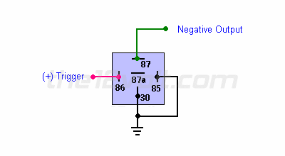
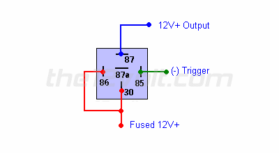
It needs to convert 12v output from the ECU to a ground signal and vica versa.  So when the ECU says 'ground' the output ends up being 12v.  And when the ECU says 12v I need the output to be ground.

I can imagine some sort of relay configuration that could make this work but because we are talking about an ignition system it must be a lot faster than a relay. 

t&t tech 
Platinum - Posts: 2,608
Platinum spacespace
Joined: October 05, 2008
Location: Trinidad and Tobago
Posted: May 26, 2009 at 5:00 PM / IP Logged  
inverting a signal -- posted image.
commit your way to jehovah and he will act in your behalf. psalms 37:5
t&t tech 
Platinum - Posts: 2,608
Platinum spacespace
Joined: October 05, 2008
Location: Trinidad and Tobago
Posted: May 26, 2009 at 5:01 PM / IP Logged  
inverting a signal -- posted image.
commit your way to jehovah and he will act in your behalf. psalms 37:5
t&t tech 
Platinum - Posts: 2,608
Platinum spacespace
Joined: October 05, 2008
Location: Trinidad and Tobago
Posted: May 26, 2009 at 5:03 PM / IP Logged  

i can't imagine why the relay won't be quick enough, but maybe the more experienced heads will explain why, and i'll learn something new,inverting a signal -- posted image.

commit your way to jehovah and he will act in your behalf. psalms 37:5
ejenner 
Member - Posts: 32
Member spacespace
Joined: December 30, 2004
Location: United Kingdom
Posted: May 27, 2009 at 3:33 AM / IP Logged  

Just because it's a mechanical switch.  The time taken for the contact to physically move inside the relay from one terminal to the other would be too long in some (if not all) firing conditions. 

Did you know many ECU's actually add compensation to fuel injector opening times to allow for different battery voltages?  Again, same scenario, because the injectors are solenoids they open relatively slowly and if you are firing your injectors sequentially rather than batch firing you will want the injector timing to be very accurate.  So as battery voltage has an effect on the opening and closing times of the injectors the ECU's compensate by allowing more time if the battery voltage is lower.

An ignition system is even less tolerant.  Just not enough time for mechanical switches to operate.  Hence why you never see them installed in ignition circuits.

KPierson 
Platinum - Posts: 3,527
Platinum spaceThis member consistently provides reliable informationspace
Joined: April 14, 2005
Location: Ohio, United States
Posted: May 27, 2009 at 7:01 AM / IP Logged  

A typical automotive electromechanical relay will switch in about 10mS.  Seems like a very short time, until you start trying to do it at 6000+ RPM!  The engine cycle is only 20mS long at 6,000 RPM and this doesn't account for seperate cylinders.

Past the timing issue, you also have wear issues -an electromechanicl relay will wear itself out pretty quickly cycling that fast whenever the engine is on.

I would either open up the ECU you are working with or ask the manufacturer to provide you with the part number for the output transistors they are using for the ignition system.  Since the current system switches to ground it can be assumed that it is either an NPN transistor or an N channel mosfet.  Once you know the part number, you can reference it to find either a PNP transistor or a P channel mosfet.  When you "inverse" the signal like this, though, you're not going to be left with a 12vdc - 0vdc pulse, you will be left with a 12vdc - open pulse.  You could use pull down resistors to pull it down close to 0vdc if needed - it all depends on how your coils fire.

Kevin Pierson
ejenner 
Member - Posts: 32
Member spacespace
Joined: December 30, 2004
Location: United Kingdom
Posted: May 27, 2009 at 12:25 PM / IP Logged  

yep, and 10ms is about 8ms longer than the normal dwell time needed for firing an ignition coil.

The ECU manufacturer would never reveal the internal workings of their ECU.  I might just ask the question on their forum to confirm this and most likely have a bit of a laugh at the same time.

KPierson 
Platinum - Posts: 3,527
Platinum spaceThis member consistently provides reliable informationspace
Joined: April 14, 2005
Location: Ohio, United States
Posted: May 27, 2009 at 1:41 PM / IP Logged  

The output transistor shouldn't be considered "confidentdial" information - in fact you should be able to open the unit up and find the transistors they are using and pull the part number off of them.  With an ECU the hardware isn't the hard part, it's the software that needs to be guarded.

Kevin Pierson
t&t tech 
Platinum - Posts: 2,608
Platinum spacespace
Joined: October 05, 2008
Location: Trinidad and Tobago
Posted: May 27, 2009 at 4:12 PM / IP Logged  
mr ejenner and kevin, points taken, i didn't know it was being involved in such a complex situation, and i learned something new, inverting a signal -- posted image.
commit your way to jehovah and he will act in your behalf. psalms 37:5

Sorry, you can NOT post a reply.
This topic is closed.

  Printable version Printable version Post ReplyPost New Topic
You cannot post new topics in this forum
You cannot reply to topics in this forum
You cannot delete your posts in this forum
You cannot edit your posts in this forum
You cannot create polls in this forum
You cannot vote in polls in this forum

  •  
Search the12volt.com
Follow the12volt.com Follow the12volt.com on Facebook
Tuesday, May 14, 2024 • Copyright © 1999-2024 the12volt.com, All Rights Reserved Privacy Policy & Use of Cookies
Disclaimer: *All information on this site ( the12volt.com ) is provided "as is" without any warranty of any kind, either expressed or implied, including but not limited to fitness for a particular use. Any user assumes the entire risk as to the accuracy and use of this information. Please verify all wire colors and diagrams before applying any information.

Secured by Sectigo
the12volt.com spacer
Support the12volt.com
Top
the12volt.com spacer