the12volt.com spacer
icon

motorcycle turn signal


Post ReplyPost New Topic
< Prev Topic Next Topic >
mattcoolgame 
Member - Posts: 2
Member spacespace
Joined: June 27, 2012
Posted: June 27, 2012 at 4:52 PM / IP Logged  
I have a 2006 vulcan 900 and I have some white led lights that light up the bike at night, they are on a constant switch so they can be on whenever I want. The question I have is I want to shut the lights off when I put my turn signals on so you can see the yellow led lights for the turn signals underneath but every wire I have tested and found it is always a toggle from ground to 12v or the other way around. Where could i find a wire that just goes from ground to 12v or 12v to ground so I can activate a relay and shut off the white lights?
i am an idiot 
Platinum - Posts: 13,672
Platinum spaceThis member consistently provides reliable informationspace
Joined: September 21, 2006
Location: Louisiana, United States
Posted: June 27, 2012 at 10:04 PM / IP Logged  
The wires you are testing are probably not toggling from 12 to ground, or vice versa.  You are simply getting a ground type reading via the light bulbs. 
mattcoolgame 
Member - Posts: 2
Member spacespace
Joined: June 27, 2012
Posted: June 27, 2012 at 10:42 PM / IP Logged  
but if I hook up a relay to those wires will the relay stay engaged or with it go on and off?
oldspark 
Gold - Posts: 4,913
Gold spacespace
Joined: November 03, 2008
Location: Australia
Posted: June 28, 2012 at 2:47 AM / IP Logged  
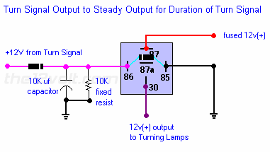
You need a circuit that senses the +12V flashes to the indicators and stays active during the off pulses.
IE - charge a capacitor though a diode...
motorcycle turn signal -- posted image.
... as from top of page Pulsed to Steady Output...
BUT without the 10k resistor (IMO not needed - nor is the diode across 85 & 86)...
AND connect the LED(s) to 87a instead of 87.
The NC (normally closed) relay contacts 30 & 87a can be either side of the LED(s) - ie, +12V supply or GND side. EG: +12V -> 87a -> 30 -> LED+ ; LED- -> GND.
The +12V pulses to 86 energise the relay (hence breaking 30-87a) and charge the capacitor.
The capacitor discharges via the relay coil. (The series diode from the flasher prevents discharging via the flasher bulbs.)
The relay hold up time is approximately RC where R is the resistance of the relay coil (Ohms) and C is the capacitance (Farads).
You want an approx 1 second delay, hence RC = 1.
You need one circuit per side unless you want all white LEDs off whichever side is flashing (in which case use a diode from EACH flasher side to the cap & relay).
howie ll 
Pot Metal - Posts: 16,466
Pot Metal spacespace
Joined: January 09, 2007
Location: United Kingdom
Posted: June 28, 2012 at 3:39 AM / IP Logged  
Shouldn't this simple idea work, use 2 x 1N5404 diodes:- indies.bmp
oldspark 
Gold - Posts: 4,913
Gold spacespace
Joined: November 03, 2008
Location: Australia
Posted: June 28, 2012 at 6:16 AM / IP Logged  
That only operates whilst lit during flashing - it's the old "how to keep off whilst flashers are off" problem (ie - a time delay to hold between flashes is needed).
It will work if it's a +12V (or GND) "constant" signal that actuates the flasher can as with dual-purpose flasher lamp circuits - ie, combined flashers and brake or reverse lights.
But most flasher switches are after the flasher can - ie, IGN +12V to the can, then the flasher switch switches to the left else right lamps (or both for hazard flashers).
FYI - I've decided to use a PIC for my flasher lamp logic - whether combined flasher/reverse, or side flasher/clearance lamps (and maybe front flasher/running lamps). Hence no RC-decay relay chatter problems, and I can use PWM for bright-flasher (else off) or dim-clearance for the sides or front.   

Sorry, you can NOT post a reply.
This topic is closed.

  Printable version Printable version Post ReplyPost New Topic
You cannot post new topics in this forum
You cannot reply to topics in this forum
You cannot delete your posts in this forum
You cannot edit your posts in this forum
You cannot create polls in this forum
You cannot vote in polls in this forum

  •  
Search the12volt.com
Follow the12volt.com Follow the12volt.com on Facebook
Tuesday, May 14, 2024 • Copyright © 1999-2024 the12volt.com, All Rights Reserved Privacy Policy & Use of Cookies
Disclaimer: *All information on this site ( the12volt.com ) is provided "as is" without any warranty of any kind, either expressed or implied, including but not limited to fitness for a particular use. Any user assumes the entire risk as to the accuracy and use of this information. Please verify all wire colors and diagrams before applying any information.

Secured by Sectigo
the12volt.com spacer
Support the12volt.com
Top
the12volt.com spacer