Geez - I was worried when I read YOUR description in the email... what had I drawn?
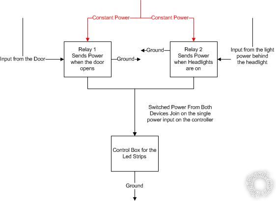
First - the good bit & good assumption; the 3 horizontal
triangularish lines are ground (GND).
The other good bit - you assuming my diagram is correct and hence your
cautious questions... but also your questioning etc - I could be wrong!!!! [ REM above "
... what had I drawn?..." ]
(Hence - in case of the rare yet still TOO oft occurrence that I might indeed be wrong - my reciprocal niceness. To quote someone else's "signature" - "no such thing as stupid questions - only stupid answers".)
Now for the remaining bits....
It's a case of learning to read wiring or circuit diagrams. It's not hard - there are references (on 12volt etc), and IMO it becomes almost intuitive once you start to understand...
But where to start? Maybe your reply, THEN my description....
"
the 30 wire is the constant power" - no,
30 is simply a contact. It could be used for anything - input, output, GND etc. But it is often connected to a power
source like
constant power.
"
i thought that the 87 wire is where the power flows to only when the coil is energized". Correct! But rather, 30 is connected to 87 when the relay is
closed or
energised. As with 30, what it is connected to is arbitrary.
"
so why does the led power wire connect to the 86 wire which is part of the coil?" - yes, it is the coil, but no - 86 is +12V when the headlights are on. So 86 comes from some part of the circuit (car) that is +12V when the headlights are on - maybe from the headlight relay's #30, or the beam switch etc.
Hence the grounded coil (thru 85) has 12V across it when the headlights are on, hence energising the relay and
flipping its heavy contacts from 87 to 87a, hence joining 30 to 87a.
"
...how a positive (from the dome light) and a negative from the door switch can join on the same wire?" - no... there are components in between, ie - they are NOT the same wire.
The top part of the dome light is +12V. Ignoring the "left-tee" to the relay, its bottom is either "floating" or grounded.
IE - the door switch(es) as shown are open - hence no electricity flow.
If it/they close, thereby "shorting" or connecting the top part of the door switch to the (grounded) bottom part, then the dome light's bottom is grounded.
Although that might give the dome light a very dirty bottom, it will also mean +12V top side and GND bottom side, hence 12V difference and it lights.
(FYI - down here we call ground "earth", and I reckon our earthed bottoms are probably dirtier than your grounded ones.

)
"
...leave the led's on when the door is shut?"...
Now let's try my explanation.
It requires understanding of the above "building blocks" - ie:-
- only lines connected together are the same "wire" (inserted components change the connection...)
-
closed contacts "join" different wires together (effectively the same wire or connection);
- think of any point on the same wire as being the same electrically;
- a "gap" in a wire or contact/switch is an open circuit (ie, no electricity flow)....
(Hopefully that's enough for now!)
Also, I draw "circuit" or functional diagrams that are supposed to show how things connect.
(As opposed to how
to connect which show
pictures of actual relays & wiring.)
Circuit diagrams generally show things in their "normal" state.
EG - the door switches are shown open (when they are Normally Open switches that closed when the door opens).
The relays are shown de-energised, and usually with the NC (Normally Closed 87) contact away from the coil. Hence my relay above, the coil "pulls" the
switch towards it.
(FYI - To simplify circuit understanding (ie, tracing it through), relay contacts may be shown remote from the coil; maybe "upside-down"; and relays/switches with many poles might be shown with poles scattered all over the place.)
So now, my explanation....

As shown, the LEDs are off.
Though the LEDs have +12V, their Kathode (bottom) goes to thru 30 to the NC contact 87 to the dome light bottom.
Since the door switch is open, neither dome nor LEDs are grounded, hence all are unlit.
If the door is opened, the door switch closes, hence grounding the dome light (as usual), AND the LEDs thru the relay 87-30.
Hence dome and LEDs are lit on with door open.
Close the door. LEDs & dome are off again (ie, the door switch opens).
Turn on headlights.
+12V from the headlights energise the relay - ie, energise the relay's coil with +12V on 86 with 85 grounded.
Hence the relay's contacts
pull in.
Hence 30 flips over to 87a (the grounded NO Normally Open contact).
Hence the LEDs light.... ie...
LEDs have +12V (top) and the LED's dirty bottom is grounded through 30 & 87a. Hence the LEDs are lit.
This has no effect on the dome light (87 is not connected to 30 or 87a).
The door will still turn on the dome light as usual. (No effect on the LEDs but they are already on.)
Turn off the headlights, +12V is removed from the relay's coil 86, the relay re-energises and its contact swings back to connect 30 to 87. Hence the LEDs now respond to the door switch.
Howz that?

??
The only issue - a slight break as the relay changes over but only when the door is open when turning headlights on or off.
The other issue - that I thought it could be done without a relay. It can be, but that involves diodes and it tricky with mixed
trigger polarities - ie, +12V headlights & 0V (GND) door switch.
When both are the same - ie, both GND or both +12V - then diodes are great.
Otherwise you need to invert one of the triggers which is effectively what the relay is doing.
(The above is essentially a relay that inverts either "signal" and the 2 diodes, but re-organised to remove the diodes. That's good old Boolean algebra at work - aka "logic".)
Incidentally, the above can be modified so that it is the door switch that turns on the relay instead. It depends on what is desired. But headlights are generally turned on less often than doors open... etc.
And modifications will be needed if either polarities are different from what I assumed, or if the door switch is NC (Normally Closed) etc.
sirfatty wrote:
| Thanks again for being so patient with me |
|
|
Well as yet you have not earned the right not to get it. (My patience that is. If you ever earn such right, I may substitute something else...)
Yes, that last bit is a LOL!
But you know the joke with all of this...?
It's a simple 5 minute explanation in person.
But that's the advantage of instant feedback and iterative & adaptable description. I hate written discussions when "teaching"!
I much prefer short iterations. (Ain't THAT a joke!!)


 Is there an easier way to do this?
Thanks
Is there an easier way to do this?
Thanks


 Printable version


