I have an electronics question that I hope someone may be of assistance in. I have very little electronics knowledge.
The question regards the modification of the turn signal circuit in my car, a 1971 Ford Maverick. This is how the circuit works:
DESCRIPTION
The parking, sport, rear, side marker and stop light circuits are controlled by the headlight switch. When the headlight switch is pulled out to the first detent, only the parking lights and side marker lights come on. When the headlight switch is pulled out to the second detent, the parking lights, side marker lights, headlights and sport lights on vehicles so equipped all come on.
OPERATION
On Thunderbird, Ford, Mercury, and Lincoln Continental a cornering light bulb is in the same light body with marker bulb on vehicles so equipped. The cornering lights are fed from the turn signal circuit in such a way that when the turn signal switch is activated, the cornering light on the turn side will burn with a steady glow.
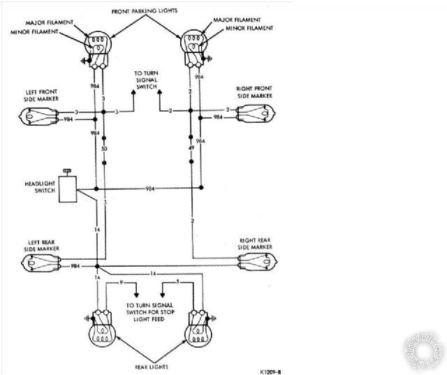
The side marker lights are connected in parallel with the feed circuit (from the headlight switch) that feeds the minor filaments of the front parking and rear lights. Each of the four side marker lights (two on each side) completes its circuit to ground through the dormant major filament of its respective left or right front parking light. Therefore the side markers glow with the parking lights.
The side markers are on when the parking (turn) light major filament is dormant providing a ground as described in the foregoing. When the turn signals are activated however, the major filament of the turn-side parking light is fed intermittently for turn signal operation. This intermittent feed interrupts the side marker lights circuit to ground causing them to go off. As a result the affected side markers for the direction of turn selected will flash alternately with the front parking/turn signal lights.
The side markers on the opposite (non-turning side) will continue to glow steadily.
The turn signal system supplies an intermittent feed to the major filament of the turn-side parking light as described in the forgoing. The same circuit also supplies and intermittent feed to the side marker lights (on the turn side) but flowing in a reverse direction from that supplied by the headlight switch when it was on. The two side marker lights complete their circuit to ground through the dormant minor filament of the turn-side parking light. Thus the side markers and front parking lights flash simultaneously with each intermittent feed. The lights on the opposite side remain off.
The emergency flasher sends intermittent power to the major filaments in both parking lights, thus interrupting the ground circuits of all four side markers. As a result, all four side markers will flash alternately with the parking lights.
Here is a link to a Maverick wiring diagram:
http://www.maverickcomet.com/defaultCookies.asp?T=397786899&UserName=&dock=&Offset=420&LOC=/Wiring/Wiring.asp
The way I understand the circuit is as follows: The rear and front markers get their ground from the front turn signal. On the left side this is via the Lt. GREEN / WHITE wire, which I believe makes the final connection to ground via the brown wire passing through the element of the bulb to ground. When the side lamp is flashing in unison with the turn light, the ground connection is made via the Lt. GREEN / WHITE wire through the minor filament (running light).
Here is my question.
For safety and aesthetics, I would like to modify the front turn signals to use an amber LED panel containing 48 5050 LEDs for the turn signal and a white 24 LED panel for the running light. With the front and rear side lamp getting their ground from the turn signal element and, to my knowledge, the LED panel not allowing a path to ground since there is no filament, Im not sure if I can accomplish this. I thought that I might be able to use a series of diodes, one of which being a grounded diode teed into the brown and supply wire of the front turn signal and the Lt. GREEN / WHITE wire of the running light. If you have any thoughts on how to make this work and the specific parts I need, I would appreciate them.
The rear tail light and stop/turn light will also be modified with one 24 LED panel for the tail light and three 24 LED panels for the stop/turn light. The turn light panels will be controlled by a sequencer. Since the side lights appear to use the front turn signal bulb for their connection to ground. I think the conversion of the rear lights to LED will not affect their operation. If someone sees differently, please let me know.
Thank you for the assistance.


 Topic Closed)


 Printable version


