the12volt.com spacer
icon

2 8 gauge wires instead of a 5


Post ReplyPost New Topic
< Prev Topic Next Topic >
aznriced 
Member - Posts: 17
Member spacespace
Joined: September 16, 2009
Location: British Columbia, Canada
Posted: March 21, 2010 at 8:31 PM / IP Logged  
Hi, currently i have a 350watt RMS alpine amp with a 8 gauge, 18ft power for my sub.   Right now whenever i try to turn the volume up at around 80 percent, the amp would cut off.
I think its because of the power wires not capable of carrying the current that the amp needs.
8 Gauge @ 18ft is 299 watts max that it can carry. And my amp needs 350. So that is why i think it cuts off.
But my real question is,
Instead of buying a 4gauge wire is it possible if i can just use 2 8 gauge wires instead. I know it technically equals to 5 gauge with both combined but would it carry the actual current as real 5 gauge wire would like this?
2 8 gauge wires instead of a 5 -- posted image.
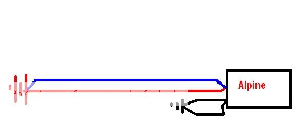
The reason this idea came up is because i have an extra set 8 gauge wires that i can use.
Thanks!
oldspark 
Gold - Posts: 4,913
Gold spacespace
Joined: November 03, 2008
Location: Australia
Posted: March 21, 2010 at 9:20 PM / IP Logged  
Buy doubling the (parallel) transmission, your are halving the resistance hence halving your voltage drop.
As you say 2x8 = 5 in terms of effective diameter.
The capability though varies eg, for "transmission", max-Amps for 5G is twice 8G as expected (47A verses 24A), but if bundled (aka chassis wiring), is is only 60% higher (118A vs 73A; Ref: powerstream.com - WireSize-Parameters&Calc-AWG).   
Ah the fun of cabling - what is an acceptable current and why (voltage drop? heating? insulation melt?).
Often multiple smaller parallels are used for incremental upgrades, adding to existing warranted wiring, better heat dissipation, limited terminal sizes, redundancy etc.
A major problem can be if there is no redundancy and one path is lost - the others may fail or burn whereas as single path usually just fails.
(Redundancy is where - if you require n devices, you have n+1 devices (or n+2 etc) so that one (or 2 etc) can fail or be taken offline for maintenance without impacting the required performance.    However, if their condition isn't monitored, it merely extends the time to failure - it won't prevent it (as many dorks have since learned).)
i am an idiot 
Platinum - Posts: 13,670
Platinum spaceThis member consistently provides reliable informationspace
Joined: September 21, 2006
Location: Louisiana, United States
Posted: March 21, 2010 at 9:38 PM / IP Logged  
Your amp needs MORE than 350 watts in to provide 350 watts of output.
aznriced 
Member - Posts: 17
Member spacespace
Joined: September 16, 2009
Location: British Columbia, Canada
Posted: March 21, 2010 at 9:40 PM / IP Logged  
oldspark wrote:
Buy doubling the (parallel) transmission, your are halving the resistance hence halving your voltage drop.
As you say 2x8 = 5 in terms of effective diameter.
The capability though varies eg, for "transmission", max-Amps for 5G is twice 8G as expected (47A verses 24A), but if bundled (aka chassis wiring), is is only 60% higher (118A vs 73A; Ref: powerstream.com - WireSize-Parameters&Calc-AWG).   
Ah the fun of cabling - what is an acceptable current and why (voltage drop? heating? insulation melt?).
Often multiple smaller parallels are used for incremental upgrades, adding to existing warranted wiring, better heat dissipation, limited terminal sizes, redundancy etc.
A major problem can be if there is no redundancy and one path is lost - the others may fail or burn whereas as single path usually just fails.
(Redundancy is where - if you require n devices, you have n+1 devices (or n+2 etc) so that one (or 2 etc) can fail or be taken offline for maintenance without impacting the required performance.    However, if their condition isn't monitored, it merely extends the time to failure - it won't prevent it (as many dorks have since learned).)
To be honest, that was pretty confusing. But are saying that
8G 24amp
5G 47amp?   
So 2 8G = 48 amp?   
But i dont need it to be that accurate as i just need it to be able to carry a little more current.
It will be like this, so not really a parallel circuit.
2 8 gauge wires instead of a 5 -- posted image.
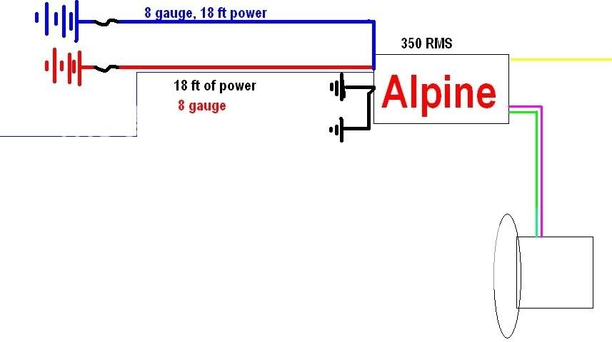
Both power cables are going to be running from the same battery with individual ring terminals all the way to the amp. Same for ground. If this matters.
So would this help give my amp the little more power that it needs?
Thanks.
i am an idiot 
Platinum - Posts: 13,670
Platinum spaceThis member consistently provides reliable informationspace
Joined: September 21, 2006
Location: Louisiana, United States
Posted: March 21, 2010 at 10:11 PM / IP Logged  

That is a parallel circuit.

Power & Ground Cable Specs
Cable Size
Wire Gauge
Current Capacity
Amperage (amps)
1/0 350
2 225
4 150
8 100
10 60
12 40
14 25
16 15

aznriced 
Member - Posts: 17
Member spacespace
Joined: September 16, 2009
Location: British Columbia, Canada
Posted: March 21, 2010 at 10:15 PM / IP Logged  
My bad, it is a parallel circuit.
The guy up there said stated those current ratings so i just followed along.   
So would 2 8G wires work/be sufficient enough for the amp?
i am an idiot 
Platinum - Posts: 13,670
Platinum spaceThis member consistently provides reliable informationspace
Joined: September 21, 2006
Location: Louisiana, United States
Posted: March 21, 2010 at 10:28 PM / IP Logged  

2 8 gauge wires will provide 200 amps of current.  However you will need to fuse each wire at 100 amps.  You should not use a 200 amp fuse and connect both wires to the fuse holder.  You need to use 2 separate fuse holders with 100 amp fuses on each.

It should be enough current for that amp.   It will be twice as good as one wire.  Have you used a meter to see if you can find the main source of the voltage drop?

oldspark 
Gold - Posts: 4,913
Gold spacespace
Joined: November 03, 2008
Location: Australia
Posted: March 21, 2010 at 10:39 PM / IP Logged  
Thanks you Idiot. Again.
Yes - that is a parallel circuit.
See www.powerstream.com/Wire_Size.htm if you didn't understand what I wrote.
For 350W RMS output, you probably want at least 35 Amps.
I suspect your amp has a 40A fuse (2x20A?) hence you should design for 40A.
This is probably too complicated for you, but JIC:
From the link above, 8G = 0.6282 R(Ohms) per 1000'.
Hence for 18' = 0.0113076 Ohms = 11.3mR (milli-Ohms were I use R for Ohms).
From V=IR (Ohms Law), V = 40A x 11.3mR = 452mV.
IE - at your 40A maximum amp current, there is a 452mV = ~0.5V drop along your single 8G cable due to the amp alone.
So your amp is probably getting whatever your battery voltage is less 1/2 a Volt.
If you halve the resistance (by doubling the cabling capacity) you halve that voltage drop (to ~0.25V). (If 4x 8G cables, then quarter it to ~0.12V etc).
The above does NOT consider the ground side, but the same applies. But I assume your grounds are short cables to chassis, hence negligible to the +12V feeds (eg, if 2', then they are 2'/18' = 1/9th the resistance of the +12V feeds, hence 1/9th the voltage drop etc). This also assumes your body/chassis has negligible resistance, but in my experience, metal cars have lower body/chassis resistance than any cabling of 0G or higher - assuming its sections are not spot welded or glued together....
If you still do not follow this, read it again and try to understand one part at a time (not necessarily sequentially - it should all come together in the end).
Is it really one simple concept, but one that is tricky to understand and apply. It's called Ohms Law. So simple. So universal.
But it can get complicated.... viz: the different current ratings that apply to the same piece of cable ( eg - 8G is 100A (Ref: Idiot) or 73A or 24A .
And maybe I should explain better or KIS. But I do add a lot as FYI...
aznriced 
Member - Posts: 17
Member spacespace
Joined: September 16, 2009
Location: British Columbia, Canada
Posted: March 21, 2010 at 11:08 PM / IP Logged  
After reading it over 20 times, i finally got it.
Thanks "oldspark" and "i am an idiot". Much appreciated for your help. :)
oldspark 
Gold - Posts: 4,913
Gold spacespace
Joined: November 03, 2008
Location: Australia
Posted: March 21, 2010 at 11:30 PM / IP Logged  
Thanks!
IMO - The fact that you got it makes you superior to MANY I have dealt with. (I'm talking intellectual superiority - whether through patience, persistence, whatever....)
It may be that my descriptions have improved thereby making it easier to understand, but come on, I think I'll keep this real!
BTW - Do not take my wire-sizing as a guide - the recommendations of "reality experts" (like Idiot, Haemo, Howie to name a few) reflect common implementations. I tend to design from first principles like V=IR after deciding a max voltage drop - I rarely refer to capacity tables. (And consequently usually over-kill cable for lighting and my standard 4x45W stereo etc!)   
And PS - I just realised the extra "s" in my last reply "Thanks you Idiot". The unsuitability of my typos often amazes me - that is so different to the intended "Thankyou Idiot".
However, in this case I shall let it go.
After all, Idiot is such an idiot - EXCEPT when it came to beating me to that name.   Grrr!!!
(And his replies in this forum are also exempted from any "idiot" status!)
Page of 2

  Printable version Printable version Post ReplyPost New Topic
You cannot post new topics in this forum
You cannot reply to topics in this forum
You cannot delete your posts in this forum
You cannot edit your posts in this forum
You cannot create polls in this forum
You cannot vote in polls in this forum

  •  
Search the12volt.com
Follow the12volt.com Follow the12volt.com on Facebook
Friday, May 3, 2024 • Copyright © 1999-2024 the12volt.com, All Rights Reserved Privacy Policy & Use of Cookies
Disclaimer: *All information on this site ( the12volt.com ) is provided "as is" without any warranty of any kind, either expressed or implied, including but not limited to fitness for a particular use. Any user assumes the entire risk as to the accuracy and use of this information. Please verify all wire colors and diagrams before applying any information.

Secured by Sectigo
the12volt.com spacer
Support the12volt.com
Top
the12volt.com spacer