the12volt.com spacer
icon

1972 fiat 124 audio upgrade difficulties


Post ReplyPost New Topic
< Prev Topic Next Topic >
branpowell606 
Member - Posts: 7
Member spacespace
Joined: May 12, 2012
Location: North Carolina, United States
Posted: May 12, 2012 at 7:52 PM / IP Logged  
Hi, I have searched many places, and I have not been able to come up with anything yet. I pulled the old head unit out, and since there is nothing resembling a wiring kit for a Fiat 2000 Spyder, I was either going to hard wire the harness that comes with my new unit(JVC KD-S38), or hope the old unit had one I could cut off, and wire into. Well, I got my wish, the old Kenwood KRC-722 has a plug harness on it that I will cut off and wire my current harness to, but it's not anything like I have seem before. The red and yellow for +12v(I assume) have small transformers wired into each input, and the ground screws straight to the unit. Do I need to cut the transformers off and use them in my new install? Second, the car does not have any sort of normal wiring that I could decipher for the speakers, instead, the head unit has two 5/180deg DIN plugs. The head unit has two, but only one is plugged into the car, the other is capped off. I assume that one goes to each set of speakers, and since this car has only one set, it only is using one. I intend to cut it off, and wire it on my new head unit adapter, but there are no markings on the old unit, and no papers that I can find anywhere to indicate which wire is which, and which is pos and neg for each speaker, etc. I have never dealt with DINs, gotta start somewhere though, right? Does anyone have any ideas or can anyone help me in getting this wiring correctly? Thanks.
DYohn 
Moderator - Posts: 10,741
Moderator spaceThis member has made a donation to the12volt.com. Click here for more info.spaceThis member has been recognized as an authority in Electrical Theory. Click here for more info.spaceThis member has been recognized as an authority in Mobile Audio and Video. Click here for more info.spacespace
Joined: April 22, 2003
Location: Arizona, United States
Posted: May 12, 2012 at 7:58 PM / IP Logged  
Check the hot topics forum for a tutorial on how to identify vehicle audio wiring.
Support the12volt.com
branpowell606 
Member - Posts: 7
Member spacespace
Joined: May 12, 2012
Location: North Carolina, United States
Posted: May 12, 2012 at 8:13 PM / IP Logged  
Thanks, I was looking for Tutorials. That is a great help in IDing the wires. What about the mini-transformers in the power and ignition wires though?
DYohn 
Moderator - Posts: 10,741
Moderator spaceThis member has made a donation to the12volt.com. Click here for more info.spaceThis member has been recognized as an authority in Electrical Theory. Click here for more info.spaceThis member has been recognized as an authority in Mobile Audio and Video. Click here for more info.spacespace
Joined: April 22, 2003
Location: Arizona, United States
Posted: May 12, 2012 at 8:14 PM / IP Logged  

branpowell606 wrote:
Thanks, I was looking for Tutorials. That is a great help in IDing the wires. What about the mini-transformers in the power and ignition wires though?

Those belong with the head unit you're removing.

Support the12volt.com
branpowell606 
Member - Posts: 7
Member spacespace
Joined: May 12, 2012
Location: North Carolina, United States
Posted: May 12, 2012 at 8:21 PM / IP Logged  
Okay, great. I suspected as much. I have been meaning to join up here for a long time, Finally had an excuse to today. Seriously though, fastest time I have ever had complete problem resolution in a forum. Thanks DYohn. You have no idea.
i am an idiot 
Platinum - Posts: 13,667
Platinum spaceThis member consistently provides reliable informationspace
Joined: September 21, 2006
Location: Louisiana, United States
Posted: May 12, 2012 at 8:51 PM / IP Logged  

The din plugs probably go to the Kenwood amplifiers.  Follow the cables to the amplifiers.  If you want to use the amplifiers, you will have to find some din plugs and make an adapter.  The layout of the dins are as follows.  looking into the end of the plug coming from the radio.  Place your right hand in front of your face, with your fingertips nearest your eyes, Pinky finger = power antenna or amp remote.  Next finger has no connection.  Middle finger = shield of RCA cable.  next finger = left signal.  Thumb = right signal.

I am second guessing myself.  It has been so long, I may have left and right backwards.

Edit, goes to THE Kenwood amplifier.

https://images.search.yahoo.com/search/images;_ylt=ArdCtUMVRN41Tww..afqQ.6bvZx4?fr=yfp-t-701-s&toggle=1&cop=mss&ei=UTF-8&p=kenwood%20din%20to%20rca%20adapter

branpowell606 
Member - Posts: 7
Member spacespace
Joined: May 12, 2012
Location: North Carolina, United States
Posted: May 12, 2012 at 9:20 PM / IP Logged  
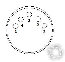
Hm, well, I decided to take apart the Kenwood, to help figure out the DIn plugs, and this is what I found:1972 fiat 124 audio upgrade difficulties -- posted image.
Plug 1, nothing
Plug 4, Red
Plug 2, Black
Plug 5, Yellow
Plug 3, White
Metal around plugs, Large Black(I assume Ground)
I didn't really care what color wires they are, I was just coming up with my own diagram to wire up the new head unit. I will look for an Amp, but I don't remember there being one. I think there is a CD changer, not sure. If so, could it be that the one DIN plug goes to the CD changer, then the changer goes to the speakers? Like I said, there is only one of the two DINs hooked up, the other is capped off. I think the one that is plugged up had a sticker that said "REAR" on it, that's why I assumed it was to the speakers. I don't see any other wires coming out of it for CD changer controls. But I could be completely wrong, it's my mom's car, and I haven't spent more then ten minutes in it. I will look and get back to you on amps and CD changers. Thx for the heads up.
branpowell606 
Member - Posts: 7
Member spacespace
Joined: May 12, 2012
Location: North Carolina, United States
Posted: May 12, 2012 at 9:25 PM / IP Logged  
The only wires that come out of the old head are two DIN plugs( only one connected) and a red, a yellow, and a blue. The red and yellow I assumed were the standard 12v+ and ignition. The blue I know is for control/remote, I think for CD changers, but it was not hooked up. Antenna wire, and a ground that bolts to the head unit from the car wiring. that's it. Two DIMs, Three wires, and antenna.
i am an idiot 
Platinum - Posts: 13,667
Platinum spaceThis member consistently provides reliable informationspace
Joined: September 21, 2006
Location: Louisiana, United States
Posted: May 12, 2012 at 9:40 PM / IP Logged  

That radio was built in 1981.  CD did not hit the car market till 85 or so.  CD changers have always needed at least an 8 pin din.  Some used 13 pin.  Kenwood may have used a different configuration of their din plugs at that time.  I know for a fact that the diagram I layed out was used in 85, and through the remainder of the din plug era. 

soundnsecurity 
Gold - Posts: 2,711
Gold spaceThis member has made a donation to the12volt.com. Click here for more info.spacespace
Joined: November 10, 2008
Location: Louisiana, United States
Posted: May 12, 2012 at 9:59 PM / IP Logged  
to avoid all this confusion i would just rewire the whole system, that way i know its good and up to date. if this is a din cable and it does go to an amp then it might be a low level signal.(?) i was born in 1986 so this is way before my time but im just used to Din cables being mainly for low level signals and things like cd changers and other random applications like networking between different pieces of equipment that are specially made to work with each other and if this is the case then hard wiring a din plug might not help you. of course i will yield my opinion to to i am an idiot's first hand knowledge, so definitely trust him before you trust me on this issue. im just giving you my .02
also i was under the impression that cd players didnt show up in cars until the early 90's at best. so perhaps this system is a little newer than expected?
Page of 2

  Printable version Printable version Post ReplyPost New Topic
You cannot post new topics in this forum
You cannot reply to topics in this forum
You cannot delete your posts in this forum
You cannot edit your posts in this forum
You cannot create polls in this forum
You cannot vote in polls in this forum

  •  
Search the12volt.com
Follow the12volt.com Follow the12volt.com on Facebook
Friday, April 26, 2024 • Copyright © 1999-2024 the12volt.com, All Rights Reserved Privacy Policy & Use of Cookies
Disclaimer: *All information on this site ( the12volt.com ) is provided "as is" without any warranty of any kind, either expressed or implied, including but not limited to fitness for a particular use. Any user assumes the entire risk as to the accuracy and use of this information. Please verify all wire colors and diagrams before applying any information.

Secured by Sectigo
the12volt.com spacer
Support the12volt.com
Top
the12volt.com spacer