the12volt.com spacer
icon

plug identification?


Post ReplyPost New Topic
< Prev Topic Next Topic >
fuster 
Member - Posts: 49
Member spaceThis member has made a donation to the12volt.com. Click here for more info.spacespace
Joined: March 05, 2010
Location: Washington, United States
Posted: February 18, 2013 at 12:52 AM / IP Logged  
plug identification? -- posted image.
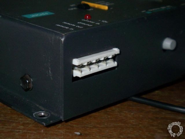
I need a plug to fit this receptacle on a Soundstream DX-7 electronic crossover. Can someone out there tell me where I can get a plug to make my wires fit into this thing? Looking at the operating manual, I likely would be using three or four wires, not all five terminals.
The terminals are for incoming power, remote power, outgoing remote power on, 12 volt constant power, ground and a "delayed remote turn on" terminal. They have another plug like this on the other end of the unit that takes incoming high level inputs if you used them, from a factory head unit.
Thanks!
Mike
Chronic, late stage optimist.
DYohn 
Moderator - Posts: 10,741
Moderator spaceThis member has made a donation to the12volt.com. Click here for more info.spaceThis member has been recognized as an authority in Electrical Theory. Click here for more info.spaceThis member has been recognized as an authority in Mobile Audio and Video. Click here for more info.spacespace
Joined: April 22, 2003
Location: Arizona, United States
Posted: February 18, 2013 at 1:09 PM / IP Logged  
I'd remove the connector and hard-wire, but you can try contacting them and see if they can sell you a wiring harness. It's an old piece though so don't hold your breath. tech-support@soundstream.com
Support the12volt.com
fuster 
Member - Posts: 49
Member spaceThis member has made a donation to the12volt.com. Click here for more info.spacespace
Joined: March 05, 2010
Location: Washington, United States
Posted: February 18, 2013 at 2:54 PM / IP Logged  
I haven't cracked it open, but I assume this plug is soldered to the board.   So to "hard wire" it I would have to solder wires into the board. I am wondering if I can at least find a screw terminal panel that has four or five terminals that I could install instead of this one. It seems like someone out there would recognize the plug and be able to refer me to an electronics parts seller that has these. I find it hard to believe that Soundstream created their own proprietary plugs.
Chronic, late stage optimist.
oldspark 
Gold - Posts: 4,913
Gold spacespace
Joined: November 03, 2008
Location: Australia
Posted: February 18, 2013 at 6:28 PM / IP Logged  
It looks like the type of connector used for double-sided PCBs (or single-sided if each finger is connected together).
They typically come in traditional 0.1" multiple spacings as well as newer and metric spacings.
IMO not good for repetitive remove & refits.
fuster 
Member - Posts: 49
Member spaceThis member has made a donation to the12volt.com. Click here for more info.spacespace
Joined: March 05, 2010
Location: Washington, United States
Posted: February 18, 2013 at 8:24 PM / IP Logged  
What can I buy to replace this with something more familiar, such as what you see that has screws to hold down wires like what you typically see coming through the case of amplifiers and processors?
There must be a recognized part name or phrase I can use to search for something on Parts Express or some other electronics supply company, right? I am happy to yank this thing and am perfectly capable of soldering in something more practical, if someone can steer me in the right direction to buy the part.
Thanks again for the help!
Mike
Chronic, late stage optimist.
Ween 
Platinum - Posts: 1,366
Platinum spacespace
Joined: August 01, 2004
Location: Illinois, United States
Posted: February 18, 2013 at 8:52 PM / IP Logged  
Get out the ruler, measure the pitch of the connector. Mouser, Allied, All Electronics, etc. have connectors which you should be able to find a comparable pitch. Then decide on a terminal block style, or male/female set...as well as determine how you'd like the one end will attach to the board.
or just have wires soldered to the board coming out of the unit.
mark
fuster 
Member - Posts: 49
Member spaceThis member has made a donation to the12volt.com. Click here for more info.spacespace
Joined: March 05, 2010
Location: Washington, United States
Posted: February 18, 2013 at 11:46 PM / IP Logged  
I looked a little for something on some of those electronics places listed. I can't fill in all the fields to do an educated search. I pull up pages of "barrier terminal pc mount" parts. They want information about things I am not familiar as far as aspects of the part. I don't know for example what they mean by "pitch". All I want is something I can mount on the case of this thing that I can solder to the board on the inside and use screw terminals on the outside.
Chronic, late stage optimist.
Ween 
Platinum - Posts: 1,366
Platinum spacespace
Joined: August 01, 2004
Location: Illinois, United States
Posted: February 19, 2013 at 5:10 AM / IP Logged  
the pitch is the spacing between two adjacent terminals/contacts. easiest way i can describe is you have five terminals. place ruler at edge of terminal one. measure over to same edge of terminal five. now divide by four. that is the pitch of the connector.
fuster 
Member - Posts: 49
Member spaceThis member has made a donation to the12volt.com. Click here for more info.spacespace
Joined: March 05, 2010
Location: Washington, United States
Posted: February 19, 2013 at 8:26 PM / IP Logged  
Thanks for that help, it is much appreciated!
Chronic, late stage optimist.
fuster 
Member - Posts: 49
Member spaceThis member has made a donation to the12volt.com. Click here for more info.spacespace
Joined: March 05, 2010
Location: Washington, United States
Posted: February 26, 2013 at 10:46 AM / IP Logged  
UPdate:
I got some help from a seller on eBay. He gave me part numbers from Mouser for a female chassis mount plug that will replace what I have, and a male plug with screw terminals. He said it is what PPI used on their OS amps. The plug will fit the opening on the metal box for the electronic crossover, and the pins fit the spacing (5 mm) needed to solder to the board. Finally, a solution!
Using those on line electronics sellers can be daunting. They are not very user friendly in terms of composing successful search queries.
Chronic, late stage optimist.

Sorry, you can NOT post a reply.
This topic is closed.

  Printable version Printable version Post ReplyPost New Topic
You cannot post new topics in this forum
You cannot reply to topics in this forum
You cannot delete your posts in this forum
You cannot edit your posts in this forum
You cannot create polls in this forum
You cannot vote in polls in this forum

  •  
Search the12volt.com
Follow the12volt.com Follow the12volt.com on Facebook
Sunday, May 19, 2024 • Copyright © 1999-2024 the12volt.com, All Rights Reserved Privacy Policy & Use of Cookies
Disclaimer: *All information on this site ( the12volt.com ) is provided "as is" without any warranty of any kind, either expressed or implied, including but not limited to fitness for a particular use. Any user assumes the entire risk as to the accuracy and use of this information. Please verify all wire colors and diagrams before applying any information.

Secured by Sectigo
the12volt.com spacer
Support the12volt.com
Top
the12volt.com spacer