It must be my week for the big 3.
At least that youtube is better than the other crap I've just seen, but I do have a few comments:
- do not touch car metal when disconnecting the battery +12V. That's true if the battery -ve is still connected, but that -ve should NEVER be connected when fitting or removing the +12V terminals (beware of secondary batteries) and hence IMO that warning is misstated.
- the 0G from the alternator has no effect except as follows:
Fat cable is important if it's a single-wire alternator (D+) but that looks like it is a 2 or more wire type - ie, it has a Sense connection to the battery +12V. Hence voltage drops across the alternator to battery cable have no impact unless that cable gets too warm or melts, or you are powering things direct from the alternator (which may not handle the higher voltage) or the alternator is pushing its highest output (at that RPM) and you want that extra bit of power (ie, less i2R losses).
I'd rather a smaller more flexible cable with copious capacity - ie, maybe a 0.1-0.2V drop at most during full output current.
Otherwise the video seems ok in principle - ie, you want to ground to chassis (frame) rather than body panels.
I have concerns about how those leads are bolted in, and I'd prefer dedicated bolts etc (ie, only one GND or only GNDs - not other mechanical components dependent on bolt torques or not having angle grinders scar threads), but your mounting points seem ok. 600W is only ~60A - it's not a huge system.
The major OEM GND is from batt- to the engine block because the starter-motor has the highest current demand (excluding 400A catalytic converters etc).
That is usually sufficient for audio systems unless the alternator has a similar current rating (noting that starters are short term and therefore that GND could be underrated for full time use).
Some vehicles might go from the batt- to the chassis and then to the engineblock but most seem to have batt- to block and batt- to chassis ie, 2 cables from the batt- terminal.
I usually add an engine to chassis GND
under the engine - eg, from unused spare block threads else engine mounts to a nearby chassis point. That's usually the shortest and subject to least vibration and heat, hence more reliable etc. And both should be able to use substantial bolts - ie, fatter than turret bolts etc.
It also means a lower GND voltage because of its lower mounting. (Just kidding re that last sentence.)
But the wiring order shouldn't matter - ie, batt- split to block & chassis or batt- to block to chassis to batt- to chassis to block.
If they are all copiously fat enough, there should be negligible voltage drop and that's the point of the big 3.
Note that those
two cables ground THREE things together.
One simple improvement is the add a third cable to the
missing section. EG - my block to chassis adds redundancy and lowers the resistance of my OEM split batt- to block & chassis wiring. (It also boosts the batt- to chassis from its
thin cable to the fatness of the batt- to block to chassis cabling.)
I'm not sure if that answers your question?
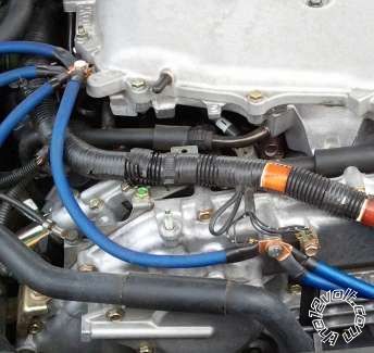
Incidentally the following is NOT how to do it...
Admittedly that's not for audio but (believe it or not!) improved engine performance!
That's courtesy of the NicoClub as discussed on mp3car's
Grounding kit in cars.


 Printable version


