the12volt.com spacer
icon

Next Upgrade Step - Got Go-Ahead fr Wife


Post ReplyPost New Topic
< Prev Topic Next Topic >
kfr01 
Gold - Posts: 2,121
Gold spaceThis member has made a donation to the12volt.com. Click here for more info.spacespace
Joined: April 30, 2003
Posted: April 03, 2005 at 8:01 PM / IP Logged  

The wife and I are working in firms in two different cities this summer.  I'll be making the 5 hour trek between cities most weekends.  During the week my commute will be ~45 min a direction to my place of work.  More driving.

On a walk today, using the above justification and my ability to bore her to death with all things technical, I got the go ahead to modify my door panels.  (go me)  My one command from her  = don't touch the kickpanels.  We're both tall and enjoy our leg room.

I drive a 2001 Sebring lxi 4 sedan.  I'm going to beat it into the ground before I sell it, so I have complete freedom to hack the panels up.  There's a "lower portion" of the door that I can easily remove much like the door here:  http://www.hzemall.com/our_gallery/installs_misc/rx7_door_panels/rx7.htm

I plan to completely remove this lower panel and construct a new one of MDF and fiberglass. 

Design goals:

1) New solid lower door panel that does not hum and resonate like the current one!

2) Bring the midrange and tweeter more on-axis
3) Soften the system.  I've found the Quart tweet just a tad bright for my more relaxed Jazz/Classical taste in music.

Plan:

1)  MDF Baffle, a sufficient amount of fiberglass, and some damping spray should solve the solidity problems.

2)  I hope to aim woofer and tweeter pod like portions of the lower corner toward my ears on both panels.
3)  I need to select a tweeter.

The midbass / midrange driver I will use is the Extremis 6.8.  I was thinking of going with either the PG Titanium Elite, Dyn 3-way system, or Morel 3-way, but the wonder driver that is the Extremis should eliminate the need for an extra driver.  I will seal the door panel "enclosure," and since I'm using the entire lower portion of the door I should be able to achieve a reasonable Qtc for crossing over to the subwoofer at 80hz.

So, I need specific tweeter suggestions.  I'd like to keep the mounting diameter small, as to increase the ease of my panel redesign. 

Here are two tweeters I did some looking at today:   

http://www.madisound.com/seas/L0001.html
http://www.dynaudio.de/eng/mobile/driver/md130.htm

Any other suggestions?  Also, is there any disadvantage, heat, vibration, etc. wise to using a home audio driver like:  http://www.madisound.com/seas/H1189.pdf   (other than large-ish diameter?)

For the crossover I am thinking one of two things:

1)  Finally put in the time to teach myself passive crossover design and build a custom crossover for the the left and right sides separately, after they are installed in the custom door panel. 

OR

2)  Use some XO/EQ combo from Altomobile or Audiocontrol. 

Comments?

New Project: 2003 Pathfinder
DYohn 
Moderator - Posts: 10,741
Moderator spaceThis member has made a donation to the12volt.com. Click here for more info.spaceThis member has been recognized as an authority in Electrical Theory. Click here for more info.spaceThis member has been recognized as an authority in Mobile Audio and Video. Click here for more info.spacespace
Joined: April 22, 2003
Location: Arizona, United States
Posted: April 03, 2005 at 9:29 PM / IP Logged  
I highly recomend the Seas Lotus tweeters.  The ones in my Ref. comp set are RT25A, which may be an earlier model number.  They are very smooth and detailed without being harsh or overly bright like a metal dome can be.  The only disadvantage besides physical size that I can think of to using a home tweeter is they can be more fragile and not last as long as those designed for autos.  The Seas 27TDF series is a commonly used DIY tweeter as the crossover can be fairly simple.
Support the12volt.com
dwarren 
Platinum - Nominee - Posts: 1,811
Platinum - Nominee spaceThis member has made a donation to the12volt.com. Click here for more info.spacespace
Joined: December 03, 2004
Location: California, United States
Posted: April 03, 2005 at 10:10 PM / IP Logged  

I really enjoy the dynaudio speakers, I have heard a number of vehicles with them and they always leave me speechless. I have no experience with Seas Lotus tweeters unfortunately.

I'd be pleased and impressed to see your hand built x-overs. If I were you, I might consider trying your hand made x-overs first, but allow  yourself  to be able change plans or be flexible with incorporating the mentioned brands above.

DYohn, have you listened to both?

kfr01 
Gold - Posts: 2,121
Gold spaceThis member has made a donation to the12volt.com. Click here for more info.spacespace
Joined: April 30, 2003
Posted: April 03, 2005 at 10:22 PM / IP Logged  
Thanks for the responses, you two.  Yes, Dyohn, have you heard the dyns at all?
New Project: 2003 Pathfinder
stevdart 
Platinum - Posts: 5,816
Platinum spaceThis member has made a donation to the12volt.com. Click here for more info.spaceThis member has been recognized as an authority in Mobile Audio and Video. Click here for more info.spaceThis member consistently provides reliable informationspace
Joined: January 24, 2004
Location: Pennsylvania, United States
Posted: April 04, 2005 at 9:34 AM / IP Logged  

kfr01 wrote:
Comments?

Seal the doors shut and climb through the windows like the Dukes of Hazzard.  Seriously.

Here's a list of calculators and stuff I have been using to figure crossovers and select components etc:

  • Resistors.  Values are added when the resistors are in parallel with each other, but added using parallel resistance calculation (1/R total = 1/R1 + 1/R2 + 1/R3 etc.)  example:  75 ohm and 56 ohm resistors in parallel = 32 ohms resistance.  Use this site's parallel calculator.  And these are good to use.  The values of watts are added together, so in the example if both resistors were 10 watts the total value would be 20 watts.  That only means that the resistors will allow at least 20 watts of power to flow through them before the heat would cause the resistance values to rise.
  • Capacitors.  Values are added by wiring capacitors in parallel, such as a 2 uF and a 4.7 uF = 6.7 uF.  A high quality capacitor can be paralleled with a lower quality cap and you end up with the tonal qualities of the higher quality if it is at least 10% of the total value (as I understand it).  Such as this 100 uF NP electrolytic and this 15 uF polypropylene in parallel for a total value of 115 uF.
  • Coils, or inductors.  Values are added when the coils are linked in series.  I use these coils

I would bet that you don't need to go to the greatly added cost of esoteric crossover components in a car system, but those who use those components like DYohn might override this guess and steer you onto the right track with appropriate component suggestions.

Use Speaker Workshop to design your crossovers.  Other calculators:  http://www.mhsoft.nl/spk_calc.asp is loaded with handy calcs.  And this site's calcs like the one I mentioned above are useful.  I bought  high quality  silver-coated wire from Handmade Electronics (in Allentown, PA.) for use in wiring my last crossover.

You can use SPL Trace to copy the manufacturer's frequency response and impedance graphs and load them into Speaker Workshop to begin crossover design.  Once you have the system complete and installed you can then go to your more exact measures of using the RTA to decide if or how you want to tweak it.  Knowing how the values of the components are added or changed, you can make slight adjustments in frequency response by simply soldering another component onto the board.

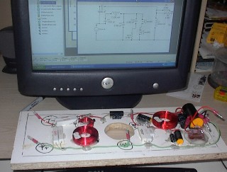
Here's the Xover I just worked on, using what I've learned primarily from DYohn and using the components I listed above.  (Speaker Workshop schematic is  on the screen).  This is on the inside back panel of the center channel speaker system I'm making:

Next Upgrade Step - Got Go-Ahead fr Wife -- posted image.

kfr01 
Gold - Posts: 2,121
Gold spaceThis member has made a donation to the12volt.com. Click here for more info.spacespace
Joined: April 30, 2003
Posted: April 04, 2005 at 9:56 AM / IP Logged  

Stevdart: 

First:  thanks for the great post! 

Second:  I would climb through the windows like the Dukes if I wasn't 100% sure that I'd hurt myself the first time.

Your post points me in the right direction.  I messed around with speaker workshop a few weekends ago for a few minutes and it seemed pretty awkward to use at first.  I might be sending you a PM or starting a thread when I have the time to mess around with it, asking for a little direction - or at least a verification that what I'm doing makes some sense.  :-)  I didn't know that the SPL Trace program existed until you mentioned it in a thread recently.  Cool program!  I think the whole speaker testing idea with those jigs and such has been my sticking point to jumping into crossover development so far. 

Thanks again

New Project: 2003 Pathfinder
stevdart 
Platinum - Posts: 5,816
Platinum spaceThis member has made a donation to the12volt.com. Click here for more info.spaceThis member has been recognized as an authority in Mobile Audio and Video. Click here for more info.spaceThis member consistently provides reliable informationspace
Joined: January 24, 2004
Location: Pennsylvania, United States
Posted: April 04, 2005 at 10:18 AM / IP Logged  

Glad to share my experience with you because you teach me so much.  Pick out a tweeter and a woofer, any one of each, from PartsExpress or Madisound and download the freq response and impedance graphs.  Practice on those first and you will have it down by the time you select your components.  You'll find that you'll sometimes want to cross over the woofer at a different freq than the tweeter to get a smoother response.  I did that with the one I showed above, the difference in the two was something like 500 Hz ( I think one was at 2500 Hz and the other was at 2000 Hz, although now I can't remember...I tried so many different configurations). 

The components in the pic are fuzzy, but in almost every case of getting the proper value I used multiple components.  Caps in the top right corner:  a large one in size but only 30 uF polypropylene paralleled with a smaller but higher value electrolytic 80 uF cap....combined to make 110 uF for the 1st order woofer highpass.  The other two crossovers are 2nd order Butterworth.  The woofer network is on the right side of the board as seen here and includes a Zobel network;  the tweeter network is shown on the left side and includes a -2 ohm Lpad.

DYohn 
Moderator - Posts: 10,741
Moderator spaceThis member has made a donation to the12volt.com. Click here for more info.spaceThis member has been recognized as an authority in Electrical Theory. Click here for more info.spaceThis member has been recognized as an authority in Mobile Audio and Video. Click here for more info.spacespace
Joined: April 22, 2003
Location: Arizona, United States
Posted: April 04, 2005 at 10:23 AM / IP Logged  

I have not heard those specific Dynaudio tweeters, although I've certainly heard their drivers many times and am familiar with the home line those are based on.  They are generally very smooth sounding and detailed and should sound very similar to the Lotus.  The sound quality difference between the Dyn and the Seas is most likely very minor in their intended frequency bands; the Seas will probably reach down a bit lower.  Dynaudio manufactures their drivers in Denmark alongside those from Vifa, Scan Speak and Peerless (although Dyn uses their own proprietary designs.)  The sound of Dynaudio drivers ends to be very similar to the high-end Scan Speak driver (which, by the way, is very good!)

As far as crossovers are concerned, some speakers are much harder to work with than others and require more complex crossovers.  I've found that (especially with tweeters) speakers on the high end and on the low end are the hardest to build proper crossovers for and those designed for the middle-of-the-road are the easiest.  Cheap tweets have terrible resonance peaks (making them sound harsh) and high Fs and very narrow acceptable response bands, although they tend to be pretty rugged.  High-end tweeters tend to require very steep slopes as they self-destruct if played too low and very specific attentuation filters to tame response peaks along with Zobels to tame impedence curves.

In general, a good place to start when designing a tweeter passive crossover is a 12db/octave or greater Butterworth design set to at least 2X the Fs of the driver.  Since the Extremis seems to work best when crossed at between 1500 and 3500 Hz, you'll need to pick a setting (say 2400Hz for grins) and choose a tweeter with an Fs at 1200Hz or lower.  You get the picture.

Support the12volt.com
DYohn 
Moderator - Posts: 10,741
Moderator spaceThis member has made a donation to the12volt.com. Click here for more info.spaceThis member has been recognized as an authority in Electrical Theory. Click here for more info.spaceThis member has been recognized as an authority in Mobile Audio and Video. Click here for more info.spacespace
Joined: April 22, 2003
Location: Arizona, United States
Posted: April 04, 2005 at 10:30 AM / IP Logged  

stevdart, nice looking crossover and good worK.  I like the way you drew out the circuit on the mounting board and then matched up components physically.  But let me point out one thing.  The two inductors on the left side of your board are aligned on axis in the same magnetic plane.  These will most likely couple magneticly and interact with one another, which will change both of their net inductance valuse.  This may or may not be an issue, but if you get unexpected performance and think you've used the wrong inductor value at this point, before you start swapping them try standing the smaller on one edge and moving it physically away from the larger one by a couple inches.  This may solve the problem (if it occurs!)

Cheers!

Support the12volt.com
stevdart 
Platinum - Posts: 5,816
Platinum spaceThis member has made a donation to the12volt.com. Click here for more info.spaceThis member has been recognized as an authority in Mobile Audio and Video. Click here for more info.spaceThis member consistently provides reliable informationspace
Joined: January 24, 2004
Location: Pennsylvania, United States
Posted: April 04, 2005 at 10:44 AM / IP Logged  

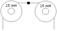
DYohn, thanks for bringing that up because I wanted to ask you about that anyway.  Those two coils were used in series to achieve .8 mH because I couldn't get a coil with that value.  I used the info I found here at PartsExpress:

"To add inductor values, they can be added in series. For example, if a value of 50 mH is desired, you can add two 25 mH inductors such that the leads are connected as shown below:"

Next Upgrade Step - Got Go-Ahead fr Wife -- posted image.

Am I correct here, then, or should I turn one on its side?

Page of 2

  Printable version Printable version Post ReplyPost New Topic
You cannot post new topics in this forum
You cannot reply to topics in this forum
You cannot delete your posts in this forum
You cannot edit your posts in this forum
You cannot create polls in this forum
You cannot vote in polls in this forum

  •  
Search the12volt.com
Follow the12volt.com Follow the12volt.com on Facebook
Saturday, June 1, 2024 • Copyright © 1999-2024 the12volt.com, All Rights Reserved Privacy Policy & Use of Cookies
Disclaimer: *All information on this site ( the12volt.com ) is provided "as is" without any warranty of any kind, either expressed or implied, including but not limited to fitness for a particular use. Any user assumes the entire risk as to the accuracy and use of this information. Please verify all wire colors and diagrams before applying any information.

Secured by Sectigo
the12volt.com spacer
Support the12volt.com
Top
the12volt.com spacer