the12volt.com spacer
icon

Zapco Z400C4-SL


Post ReplyPost New Topic
< Prev Topic Next Topic >
scott-leanne 
Member - Posts: 2
Member spacespace
Joined: March 10, 2006
Location: United States
Posted: March 10, 2006 at 11:48 PM / IP Logged  

I'm working on this amplifier and need to find info on some semiconductors that zapco used in this thing. They are to92 type and they are on the front end of the amp. The part numbers on the transistors and locations on the board are; Q41-c436aj, Q48-c436aj, Q49-c448ab, Q54-c436aj, Q55-c448ab, Q60-c436aj, Q65-c448ab, Q72-c448ab. I've tried to cross them and find data sheets with no luck.  With them out of circuit, two of the three legs show about 4ohms in either direction on both types and on the exact two legs. The middle leg to the third leg shows high resistance. I'm stuck. Don't know if they are regulators or some kind of mosfets or just bad transistors. The four 100uf caps in the same section did leak their electrolytic fluid. All the surface mount transistors in the area do not show any shorts.  Would like to know what could work in there place. Any help would be greatly appreciated.

Scott

scott-leanne 
Member - Posts: 2
Member spacespace
Joined: March 10, 2006
Location: United States
Posted: May 14, 2006 at 10:00 AM / IP Logged  
I found the problem and thought I would share.

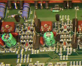
The caps did leak and replacing them is all that I did. THEY DID NOT DAMAGE the board.

Zapco Z400C4-SL -- posted image.

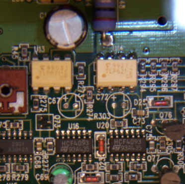
I found a timing issue with a HCF4093 QUAD 2 INPUT NAND SCHMITT TRIGGER located at U20.

Zapco Z400C4-SL -- posted image.

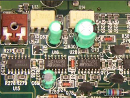
The 10uf 50v cap (C72) connected to pins 12 and 13 was making the amp not start all the time. I found this when I removed the cap and the amp started every time. I opted to put a 100uf 50v cap in its place and everything works fine.

Zapco Z400C4-SL -- posted image.

So after replacing all the out-put finals, power supply MOSFET’s, full wave bridge, all 12 SMD op-amps and many caps, it turned out to be just the four leaking caps in the preamp stage and the timing issue. It sucked working on a four layer board without a schematic!, THANKS ZAPCO FOR ALL YOUR HELP! (NOT). Just thought I would share.

Scott

Back together…

Zapco Z400C4-SL -- posted image.


Sorry, you can NOT post a reply.
This topic is closed.

  Printable version Printable version Post ReplyPost New Topic
You cannot post new topics in this forum
You cannot reply to topics in this forum
You cannot delete your posts in this forum
You cannot edit your posts in this forum
You cannot create polls in this forum
You cannot vote in polls in this forum

  •  
Search the12volt.com
Follow the12volt.com Follow the12volt.com on Facebook
Monday, April 29, 2024 • Copyright © 1999-2024 the12volt.com, All Rights Reserved Privacy Policy & Use of Cookies
Disclaimer: *All information on this site ( the12volt.com ) is provided "as is" without any warranty of any kind, either expressed or implied, including but not limited to fitness for a particular use. Any user assumes the entire risk as to the accuracy and use of this information. Please verify all wire colors and diagrams before applying any information.

Secured by Sectigo
the12volt.com spacer
Support the12volt.com
Top
the12volt.com spacer