Subwoofer enclosures with electronic assist
Definition: a subwoofer system design consisting of a sub, amp, enclosure, crossover, and an equalizer, that combines all of the qualities and abilities of these items to maximize the subs performance. In this type of design the vehicle that the sub will end up in as well as all of the above components are factored in before the final box size or tuning is decided on.
Using a simple adjustable subsonic filter and a single band EQ a person can augment a subwoofer system and accomplish the following.
1. Achieve higher output
2. Decrease cone excursion
3. Decrease distortion
4. Decrease enclosure size
5. Lower tuning frequency without sacrificing output or increasing box size
6. Achieve more relaxed, effortless and natural sounding bass at higher volumes for all types of music.
7. Reduce a subwoofer systems power requirements
In a nut shell what we want to do here is combine a subsonic filter as a high pass crossover together with the normal low pass crossover that you use with all subs. These two crossovers make an electronic band pass.
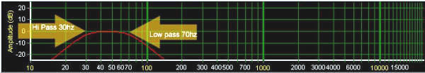
Here you can see what this looks like at the electronic level in a frequency vs. amplitude plot
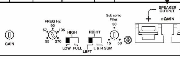
And here you can see what the settings on an amp might look like to accomplish this.
Examples of this type of design in every day use
1. Pretty much every powered subwoofer for computer use on the market today.
Ever wonder how the heck they squeeze so much bass out of such a small box? Ever wonder why they are almost always ported? Sure its not shaking the pictures off the wall, but its tiny, and draws all of its power from a little power supply that puts out less than an amp at 18 volts.
2. Pretty much every factory car audio system with a sub. Again you are not going to win any spl competitions, but remember what type of cost, power, weight, and enclosure limitations that factory engineers have to work with.
In both of these cases the audio engineers simply work miracles with box design and equalization. The key to all of this is to account for equalization and crossovers and incorporate them into your design beforehand.
3. Most pro audio subs used for concerts and night clubs
Now let me first start by stating that there is no free lunch, but there is likely a lot of food left on your plate that you have overlooked!
A subwoofer system has two main limitations, thermal (expressed in watts) and mechanical (expressed in inches or millimeters as cone displacement).
Knowing what your subwoofer systems limitations are and how to deal with them is key.
The problem
Speaking in generalizations, the problem is that most subwoofers run into one or both of these limitations well before maximum acoustic performance is achieved. The result is a subwoofer that is constantly running on the edge of its limitations or redline if you will. If you are concerned about sound quality or high spl or both you might want to consider switching gears.
Example 1
The goal in this first example is to reduce box size with out compromising output, or frequency response.
Also we dont want diminished response times or a dramatic increase in cone movement.
Sub - Image Dynamics IDQ12D2v.2
Amp Zapco Dc500.1
Subsonic filter and EQ not setup
Enclosure size 1.5 cu.ft Net, Fb 28hz, F3 30hz,
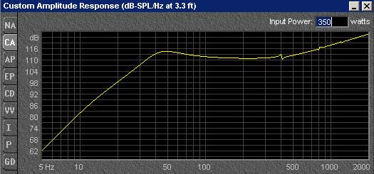
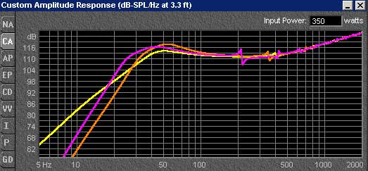
This is how the IDQ12s response looks in the factory recommended 1.5 cu.ft enclosure in free space.
Now if I reduce box size to 1 cu.ft, retune to 32hz and add a subsonic filter at 32hz and 6 db of boost at 32hz I can achieve roughly the same thing in a smaller box.
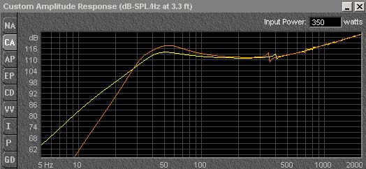
Here the orange line represents the frequency response of the 1cu.ft enclosure. The F3 is an almost identical 29.49hz and this arrangement will play louder at all frequencies across the entire pass band. Notice how much faster the orange line drops off below the F3 down point. This is because we have created a higher order enclosure. Once this enclosure is loaded into a vehicle the 1 cu.ft enclosure will only have slightly less output (about 3 db) than the 1.5 cu.ft counterpart between 20 and 25hz. This is well below most program material. Unless you are listening to test tones this is pretty much impossible to perceive in this case.
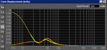
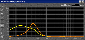
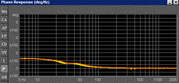
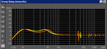
As you can see from the graphs below, cone displacement, vent velocity, phase response, and group delay are all well with in acceptable ranges as well.
Example2
Now lets say that you have room enough for a decent sized enclosure and you just want to maximize performance as a whole. You might want to try something like this on for size.
1.5 cu.ft, Fb 27hz, F3 23.51hz (pink line)
This time with subsonic set to 25hz, and 6 db of boost at 25hz
As you can see this setup will play deeper and louder with better cone control at very low frequencies. This type of setup is also ideal for marine and convertible top applications where the sub fires out into the open and there is no cabin loading that you can take advantage of.
I simply dont have the time or space here to go into all of the finer details on this subject. There are many variables and options left to explore. There is a huge amount of information out there on this subject. Some places to look are Voice Coil Magazine, Speakerbuilder Magazine, and AES (Audio Engineering Society) Journal articals.


 Printable version


