the12volt.com spacer
icon

electric windows issue


Post ReplyPost New Topic
< Prev Topic Next Topic >
twinpawer 
Member - Posts: 20
Member spacespace
Joined: April 11, 2008
Location: Malta
Posted: April 11, 2008 at 11:28 AM / IP Logged  
Hi,
    I've been having some problems with my electric windows motors. They are 2 aftermarket motors, not the ones that came originally with my car. I have 2 motors (it's a 2-door car). The driver-side motor works fine, the window goes up and down quite smoothly. However, the passenger side motor is very slow to go up, and most of the time it refuses to go up it is has been slided downmost, and it would need some manual help by hand, to have the power to push it back up.
    I've recently taken the door cards, and tried testing a bit with it. If I make a direct wire from battery to the motor, the motor works brilliantly. So I thought the issue was that the wires that connect the passenger motor with the driver are too thin. (The driver side can control both driver side and passenger side). Also, it is much slower to go up when controlling it from the driver side, than from the passenger side. I tried using a thicker wire (about 3x the original size), and it still went up very slowly, just slightly better. Any ideas what I can do to fix the problem? Any help would be greatly appreciated!
Thanks!
chriswallace187 
Gold - Posts: 1,661
Gold spacespace
Joined: March 11, 2002
Location: Pennsylvania, United States
Posted: April 12, 2008 at 3:56 AM / IP Logged  
Most of the window setups I've seen have a counterbalance spring which works to assist the window rolling up...basically it exerts a constant upward pressure on the window, rolling the window down compresses it and it relaxes as the window is rolled up.
Check to see if that spring might be screwed up on the passenger side. I've seen them break after so many years.
Also check the rubber guides and the regulator - try putting grease in them(clear silicone grease in the rubber guides, just about any grease in the metal regulator).
C Renner's Auto Electronix
My service is cheap, quick, and good - pick any two
twinpawer 
Member - Posts: 20
Member spacespace
Joined: April 11, 2008
Location: Malta
Posted: April 12, 2008 at 7:35 AM / IP Logged  
I've tried already putting silicon grease, to no avail. As for the spring, both sides do not have any spring. The thing is that if I connect the passenger-side motor directly with the battery, it works pretty well, so I think it is an electrical issue and not to do with the window itself, what do you think?
chriswallace187 
Gold - Posts: 1,661
Gold spacespace
Joined: March 11, 2002
Location: Pennsylvania, United States
Posted: April 12, 2008 at 1:09 PM / IP Logged  
I would say your next step is to get a DMM and measure resistance on the wires and switches - your resistance on all wires and switches should be less than 50 milliohms.
C Renner's Auto Electronix
My service is cheap, quick, and good - pick any two
natsys 
Copper - Posts: 87
Copper spacespace
Joined: October 11, 2002
Location: United States
Posted: April 12, 2008 at 1:10 PM / IP Logged  
Have you tried changing your switches? If you can swap the driver's window switch with the passenger switch it will tell you a lot. Since direct to the battery works fine, the problem can't be the motor, regulator, or window mechanism. The problem sounds like the motor isn't getting enough amps. If changing switches makes the driver's window slow you probably have a bad switch. If the problem still stays with the passenger window then suspect the wiring.
Where did you tie in the window kit main power? It should not be to an ignition or accessory circuit as that will not have enough for the windows and everything else the Car manufacturer ran off of it. It should be off of a relay that is powered up by an ign. circuit, but switches a fused, direct feed from the battery. If you wired it differently, try moving the supply voltage for the window kit directly to the battery (fused, of course) to see if the performance changes. I doubt the window kit manufacturer used less than the correct gauge wire for the kit, but you might check where the wires go from the door jamb into the door panel. If they're getting kind of worn you may have enough to make a connection, but not a good one. If you suspect the wires are wearing thin, replace them. And check both doors and jambs. The power to the passenger unit probably comes from the master switch in the driver's door.
twinpawer 
Member - Posts: 20
Member spacespace
Joined: April 11, 2008
Location: Malta
Posted: April 13, 2008 at 5:20 AM / IP Logged  
First of all, this is an aftermarket kit, and not an original one. I had fitted it myself some 2 years ago. As regard to the ignition, yes they are directly connected to the ignition. I'll try wiring it to a relay instead. I had changed it some few months ago to the ignition, because it was wired permanently to the battery, and it had leds in the switches which I suspected were a constant drain to the battery. However, when I changed from battery to ignition, the change wasn't very much visible, but I'll still give it a try. As for the switches, I don't think I'll be able to find a replacement, since they are made to fit with the kit (same design, etc...). Would it be possible to wire some form of relays, that the switches operate the relay and the relay operates directly the window motor? The problem is that the motor uses the same wire, but different polarity for rolling up or down. Is it possible with some form of diodes or something like that?
twinpawer 
Member - Posts: 20
Member spacespace
Joined: April 11, 2008
Location: Malta
Posted: April 13, 2008 at 5:47 AM / IP Logged  
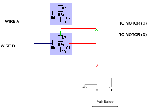
I'm not sure if this works, but I tried to do a simple diagram with how to wire them directly to the battery (with the switched wire instead of operating the motor directly, it operates the relays).
Currently, the passenger-side motor has 2 wire inputs, lets call them wire A and B. When the polarity is A+ve, B -ve, it goes up, and A-ve and B+ve, it goes down. The diagrams hows how I think it might be connected. It requires 2 other relays for wire B, where wire A is replaced with wire B, and the outputs C and D are reversed.
electric windows issue -- posted image.
Do you think this might be possible? Because this way I could work it directly to the battery, and keep the existing switches!
i am an idiot 
Platinum - Posts: 13,669
Platinum spaceThis member consistently provides reliable informationspace
Joined: September 21, 2006
Location: Louisiana, United States
Posted: April 13, 2008 at 7:04 AM / IP Logged  

electric windows issue -- posted image.

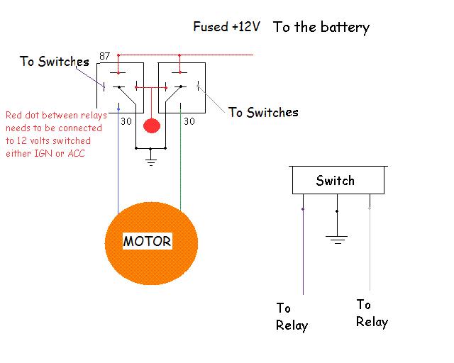
You can connect both switches to the relays.    This setup is called a reversal rest at ground.  whenever 1 relay is energized it will put a positive voltage on one wire, the other stays at ground.  If the passenger and driver switch are trying to do 2 different directions, it will not hurt a thing.  If that does happen there will be positive voltage on both wires. nothing will happen.

EDIT   I just re-read your last post, what you were attempting would work.  I didn't see that there were going to be 2 more relays for wire B.  That will work, but you only need 2 relays if done as in my diagram.

natsys 
Copper - Posts: 87
Copper spacespace
Joined: October 11, 2002
Location: United States
Posted: April 13, 2008 at 8:28 AM / IP Logged  
That illustration is real nice. It will work good for rest at ground power windows.
One word of caution though. Not all power window switches rest at ground. Some rest at positive. Before you wire anything up use a DVM (you probably could get away with a test light on aftermarket power windows) to determine the polarity of the switch outputs.
i am an idiot 
Platinum - Posts: 13,669
Platinum spaceThis member consistently provides reliable informationspace
Joined: September 21, 2006
Location: Louisiana, United States
Posted: April 13, 2008 at 8:50 AM / IP Logged  

Thanks for pointing that out.  I saw the red wires going to the relays in his diagram and I assumed that they were going to the positive terminal of the battery, since they were red wires.  But I just noticed that they go to the negative terminal of the battery.   A couple of adjustments are in order for my diagram.  The Red dot is now a ground and the grounded terminal of the switch needs to go to the switched power source.    Thanks for looking out.

Page of 3

  Printable version Printable version Post ReplyPost New Topic
You cannot post new topics in this forum
You cannot reply to topics in this forum
You cannot delete your posts in this forum
You cannot edit your posts in this forum
You cannot create polls in this forum
You cannot vote in polls in this forum

  •  
Search the12volt.com
Follow the12volt.com Follow the12volt.com on Facebook
Wednesday, May 1, 2024 • Copyright © 1999-2024 the12volt.com, All Rights Reserved Privacy Policy & Use of Cookies
Disclaimer: *All information on this site ( the12volt.com ) is provided "as is" without any warranty of any kind, either expressed or implied, including but not limited to fitness for a particular use. Any user assumes the entire risk as to the accuracy and use of this information. Please verify all wire colors and diagrams before applying any information.

Secured by Sectigo
the12volt.com spacer
Support the12volt.com
Top
the12volt.com spacer