the12volt.com spacer
icon

viper 530t modification


Post ReplyPost New Topic
< Prev Topic Next Topic >
bstegner 
Member - Posts: 6
Member spacespace
Joined: December 29, 2005
Location: United States
Posted: June 25, 2008 at 6:43 PM / IP Logged  

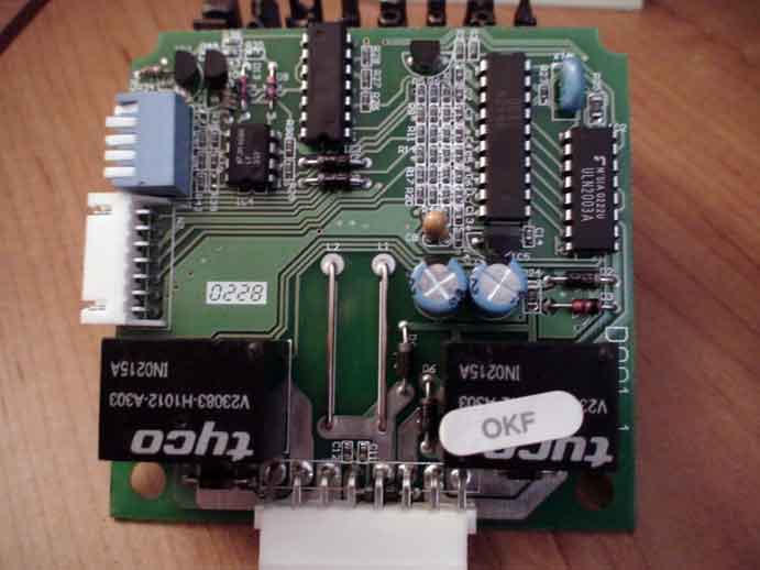
I am trying to figure out what resistors I need to replace/remove on my 530t but I am having a hard time matching it to any of the diagrams on the modification instructions ( https://www.the12volt.com/installbay/file.asp?ID=709).  My date code is OKF, if it helps, on the 530t plastic case it has a date of 9/02 on it and I had bought it 2 years ago from an ebay dealer.

viper 530t modification -- posted image.

i am an idiot 
Platinum - Posts: 13,674
Platinum spaceThis member consistently provides reliable informationspace
Joined: September 21, 2006
Location: Louisiana, United States
Posted: June 27, 2008 at 7:44 PM / IP Logged  
Somewhere on your camera there is a picture of a flower.  This switches your camera to Macro mode.  It is used to take extreme close up pictures.  Set your camera to that setting,  I need you to take a picture of the top left section of the circuit board.  Try putting the camera a little closer than you had it for the last picture.  Take a few and post the clearest one.  I am pretty sure you have to do the mod on the bottom of the page.  The board needs to be rotated 90 degrees counter colckwise.  I will rotate it and highlight the parts you need to change.
bstegner 
Member - Posts: 6
Member spacespace
Joined: December 29, 2005
Location: United States
Posted: June 28, 2008 at 12:45 PM / IP Logged  

Thanks for your help.  After reading where you want me to take a pic of, I was able to map my board to the Diagram D on the instructions.  Now all I got to do is figure out how to remove the two tiny resistors without messing up the other ones.  :)

Thanks again for your help.

i am an idiot 
Platinum - Posts: 13,674
Platinum spaceThis member consistently provides reliable informationspace
Joined: September 21, 2006
Location: Louisiana, United States
Posted: June 28, 2008 at 10:19 PM / IP Logged  
You will need to get a decent soldering iron with a small tip. Heat the iron up and add solder to both sides of the resistor you need to remove. The reason for adding the solder is to have more mass there to retain the heat and keep the solder melted longer. After adding the solder, heat up one side of the resistor, quickly move to the other end of the resistor heating it up. Switch back to the other side, the resistor should at this point be able to move by now. Gently move the resistor with the iron, once it is off of the spot gently pick the iron off of the board, the resistor should stay attached to the iron.

Sorry, you can NOT post a reply.
This topic is closed.

  Printable version Printable version Post ReplyPost New Topic
You cannot post new topics in this forum
You cannot reply to topics in this forum
You cannot delete your posts in this forum
You cannot edit your posts in this forum
You cannot create polls in this forum
You cannot vote in polls in this forum

  •  
Search the12volt.com
Follow the12volt.com Follow the12volt.com on Facebook
Saturday, May 18, 2024 • Copyright © 1999-2024 the12volt.com, All Rights Reserved Privacy Policy & Use of Cookies
Disclaimer: *All information on this site ( the12volt.com ) is provided "as is" without any warranty of any kind, either expressed or implied, including but not limited to fitness for a particular use. Any user assumes the entire risk as to the accuracy and use of this information. Please verify all wire colors and diagrams before applying any information.

Secured by Sectigo
the12volt.com spacer
Support the12volt.com
Top
the12volt.com spacer