I was hoping that you guys could look over my diagram for an install I'll be doing hopefully this weekend, so the sooner you guys could help, the better. I've installed a couple 791xv's a few years ago but I can't remember yesterday, let alone what I did for the installs. Check the wiring and let me know if I need to add any relays or diodes, or if my wiring is wrong, etc.
I'll add vehicle wiring colors in a little bit. Also not sure which door lock/unlock wire to use on my car:
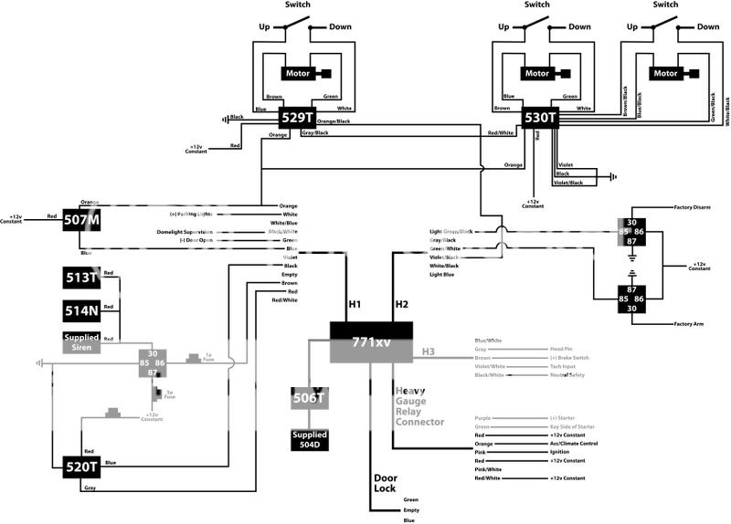
DIRECTWIRE WIRING INFORMATION - SUBARU / FORESTER / 2004 / Remote Start
12volts white + ignition harness
Starter WHITE/ blue + ignition harness
Second Starter N/A
Ignition green + ignition harness
Second Ignition N/A
Third Ignition N/A
Accessory yellow + ignition harness
Second Accessory N/A
Keysense WHITE/ red + ignition harness
Power Lock RED / white - gray plug at integrated module
Notes: The integrated module is to the left of the steering column.
Power Unlock yellow/red - gray plug at integrated module
Notes: The integrated module is to the left of the steering column.
Lock Motor lt. GREEN/ black 5wi blue plug at integrated module
Notes: The integrated module is to the left of the steering column.
Unlock Motor red 5wi blue plug at integrated module
Notes: The integrated module is to the left of the steering column.
Parking Lights+ BLACK/ red or orange + parking switch
Parking Lights- BLACK/ pink - lighting switch
Notes: The negative parking lights wire only works with the ignition on.
Hazards same as turn signal wires
Turn Signal(L) BLACK/ green + steering column or keyless
Notes: The keyless entry control module is above the passenger kick panel.
Turn Signal(R) lt. GREEN/ black + steering column or keyless
Notes: The keyless entry control module is above the passenger kick panel.
Reverse Light BROWN / yellow + passenger kick, harness to rear
Door Trigger yellow - gray plug at integrated module
Notes: The integrated module is to the left of the steering column.
Dome Supervision use door trigger wire
Trunk/Hatch Pin common with door trigger wire
Hood Pin N/A
Trunk/Hatch Release N/A
Power Sliding Door N/A
Factory Alarm Arm factory remote only
Factory Alarm Disarm factory remote only
Disarm No Unlock factory remote only
Tachometer green ac ECM, 35 pin plug, pin 10
Notes: The ECM (Engine Control Module) is below the glove box. The tach wire is also found behind the instrument cluster in the middle plug.
On the turbo models, the tach wire is in the 34 pin plug, pin 23.
Wait to start N/A
Brake Wire WHITE/ black + brake pedal switch
Parking Brake lt. green to lt. GREEN/ black - parking brake switch
Horn Trigger RED / green - steering column or keyless
Notes: The keyless entry control module is above the passenger kick panel.
Memory Seat 1 N/A
Memory Seat 2 N/A
Memory Seat 3 N/A
Interface Module: Category:
Required:
No Type:
N/A
Part #: N/A
Notes: N/A


 Topic Closed)


 Printable version


