the12volt.com spacer
icon

2004 f150, spy remote start


Post ReplyPost New Topic
< Prev Topic Next Topic >
majorgerman 
Member - Posts: 3
Member spacespace
Joined: May 05, 2009
Location: Texas, United States
Posted: May 18, 2009 at 10:01 PM / IP Logged  
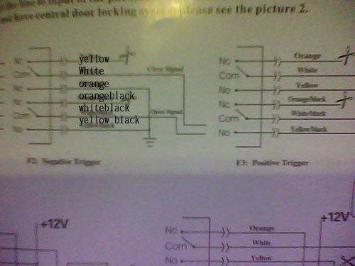
this is my first car alarm installation and im a little confused according to the diagram the door lock has to be white to close signal then white black to open signal i installed these in the pink yellow and the pink green wires at the door boot, then according to the alarm i have to install the orange and yellow black to the negative which i did but its not working!!   
Central Locking -
Yellow: Nc
Y/Black: No
White: Com
W/Black: Com
Orange: Nc
O/Black: No
then ar
2004 f150, spy remote start -- posted image.
KarTuneMan 
Platinum - Posts: 7,056
Platinum spaceThis member has made a donation to the12volt.com. Click here for more info.spaceThis member consistently provides reliable informationspace
Joined: December 14, 2004
Location: Isle Of Man
Posted: May 18, 2009 at 11:10 PM / IP Logged  

N.C., N.O., and common are the pins on a standard relay!

The ones that are labeled common are the output from the relay (pin 30)

take these to the lock/unlock on the truck.

To have this output show ground, you need to ground the N.O.'s

The N.C. will not be used.

majorgerman 
Member - Posts: 3
Member spacespace
Joined: May 05, 2009
Location: Texas, United States
Posted: May 19, 2009 at 11:12 PM / IP Logged  
i installed the wires accordingly and it unlocks locks with the remote of the car alarm but the unlock lock buttons on either of the doors do not work,, i also used the original remote and it works as well ,, i was thinking of installing the wires to the part where the remote sends the signal but i have no clue where that is
i am an idiot 
Platinum - Posts: 13,667
Platinum spaceThis member consistently provides reliable informationspace
Joined: September 21, 2006
Location: Louisiana, United States
Posted: May 19, 2009 at 11:54 PM / IP Logged  
Without being there, it is kind of hard to help you. Can you draw a diagram of what you did? Or can you give us the wiring info you used?
t&t tech 
Platinum - Posts: 2,608
Platinum spacespace
Joined: October 05, 2008
Location: Trinidad and Tobago
Posted: May 22, 2009 at 5:45 AM / IP Logged  
i noticed you said you used the original remotes and they work, which means the truck came with keyless entry, which would also mean they are negative trigger, so i'm assuming you hooked to the WHITE/ red and BLACK/ white trigger wires, if so, and either of the switch controls no longer fuction, insert two one amp diodes between the lock/unlock trigger wire of the alarm and the lock/unlock trigger wire of the truck, and post back with your results. cheers
commit your way to jehovah and he will act in your behalf. psalms 37:5

Sorry, you can NOT post a reply.
This topic is closed.

  Printable version Printable version Post ReplyPost New Topic
You cannot post new topics in this forum
You cannot reply to topics in this forum
You cannot delete your posts in this forum
You cannot edit your posts in this forum
You cannot create polls in this forum
You cannot vote in polls in this forum

  •  
Search the12volt.com
Follow the12volt.com Follow the12volt.com on Facebook
Sunday, April 28, 2024 • Copyright © 1999-2024 the12volt.com, All Rights Reserved Privacy Policy & Use of Cookies
Disclaimer: *All information on this site ( the12volt.com ) is provided "as is" without any warranty of any kind, either expressed or implied, including but not limited to fitness for a particular use. Any user assumes the entire risk as to the accuracy and use of this information. Please verify all wire colors and diagrams before applying any information.

Secured by Sectigo
the12volt.com spacer
Support the12volt.com
Top
the12volt.com spacer