the12volt.com spacer
icon

2000 v6 mustang, viper 5501


Post ReplyPost New Topic
< Prev Topic Next Topic >
cpuguy06 
Copper - Posts: 94
Copper spaceThis member has made a donation to the12volt.com. Click here for more info.spacespace
Joined: April 04, 2004
Location: Nebraska, United States
Posted: October 08, 2009 at 7:51 PM / IP Logged  
Just bought a Viper 5501 (2-way remote start with LCD remote no security). I was able to match up most wires with their appropriate vehicle wires. However, I'm confused about the connections on the heavy gauge inline connector. I have done 4 of these before and am somewhat familiar with remote starts. According to this post: https://www.the12volt.com/installbay/forum_posts.asp?tid=27386&KW=2000+mustang+lights my 2000 Mustang has 4 ignitions that need to be activated when the car starts.
Ignition #1 - Primary Ignition
Ignition #2 - Powers Blower Motor
Ignition #3 - Powers Airbag Monitor
Ignition #4 - Powers Heat/AC Controls
My question is how do I wire these all up to work with my 5501? Do I need a relay for each ignition besides the first one? Below is how the viper describes each of the wires on this heavy gauge inline connector:
1 PINK (+) IGNITION 1 INPUT/OUTPUT
2 RED / WHITE (30A) FUSED IGNITION 2 / FLEX RELAY INPUT 87
3 ORANGE ACCESSORY OUTPUT
4 VIOLET (+) STARTER OUTPUT (CAR SIDE OF THE STARTER KILL WIRE)
5 GREEN (+) STARTER INPUT (KEY SIDE OF THE STARTER KILL WIRE)
6 RED (+) FUSED (30A) IGNITION 1 INPUT
7 PINK/WHITE (+) IGNITION 2 / FLEX RELAY OUTPUT
8 PINK/BLACK FLEX RELAY INPUT 87A key side (if required) of FLEX RELAY
9 RED / BLACK FUSED (30A) ACCESSORY/STARTER INPUT
Thanks in advance people!
tommy... 
Gold - Posts: 1,901
Gold spacespace
Joined: December 10, 2004
Location: United States
Posted: October 08, 2009 at 9:09 PM / IP Logged  

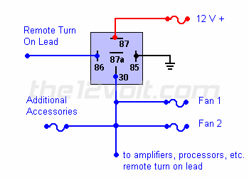
That unit(5501) should have 2 (+) ignition outputs...That should cover 2 of them...You can use a relay to power the third ignition...The 4th ignition is the Accessory wire and just use the Accessory output on the 5501...! This diagram should work for powering up third ignition...So instead of fans it goes to third ignition...!

2000 v6 mustang, viper 5501 -- posted image. Connecting Additional Devices to the Remote Turn On Wire ( link)
Using a 30 amp SPDT relay, connect terminal #87 to constant 12 volts positive with a fuse rated to the sum of the additional accessories you've added and the components you need to turn on. (If you have two fans rated at 5 amps each and a neon light rated at 10 amps, you would use a 20 amp fuse plus 200 ma for each amplifier and processor.) Connect terminal #85 to ground, terminal #86 to the remote turn on wire from the head unit, and terminal #30 to each accessory with an appropriate fuse. A fuse (not shown) could also be used between the output of the relay (#30) and the remote turn on wire of the amplifiers and/or processors for extra precaution.
 
2000 v6 mustang, viper 5501 -- posted image.

M.E.C.P & First-Class
Go slow and drink lots of water...Procrastinators' Unite...Tomorrow!
cpuguy06 
Copper - Posts: 94
Copper spaceThis member has made a donation to the12volt.com. Click here for more info.spacespace
Joined: April 04, 2004
Location: Nebraska, United States
Posted: October 14, 2009 at 8:05 AM / IP Logged  
I have been doing some searching around here and there seems to be multiple wires for the ignition 2/4. Has anyone done an install on this specific vehicle before? Should I just follow the DirectWire diagrams that have been posted on the internet?

Sorry, you can NOT post a reply.
This topic is closed.

  Printable version Printable version Post ReplyPost New Topic
You cannot post new topics in this forum
You cannot reply to topics in this forum
You cannot delete your posts in this forum
You cannot edit your posts in this forum
You cannot create polls in this forum
You cannot vote in polls in this forum

  •  
Search the12volt.com
Follow the12volt.com Follow the12volt.com on Facebook
Friday, April 26, 2024 • Copyright © 1999-2024 the12volt.com, All Rights Reserved Privacy Policy & Use of Cookies
Disclaimer: *All information on this site ( the12volt.com ) is provided "as is" without any warranty of any kind, either expressed or implied, including but not limited to fitness for a particular use. Any user assumes the entire risk as to the accuracy and use of this information. Please verify all wire colors and diagrams before applying any information.

Secured by Sectigo
the12volt.com spacer
Support the12volt.com
Top
the12volt.com spacer