the12volt.com spacer
icon

mux port on a 5901


Post ReplyPost New Topic
< Prev Topic Next Topic >
rcavictor 
Member - Posts: 35
Member spacespace
Joined: January 26, 2010
Location: Quebec, Canada
Posted: September 03, 2010 at 8:23 AM / IP Logged  

mux port on a 5901 -- posted image.

Hello 12Volts friends ,

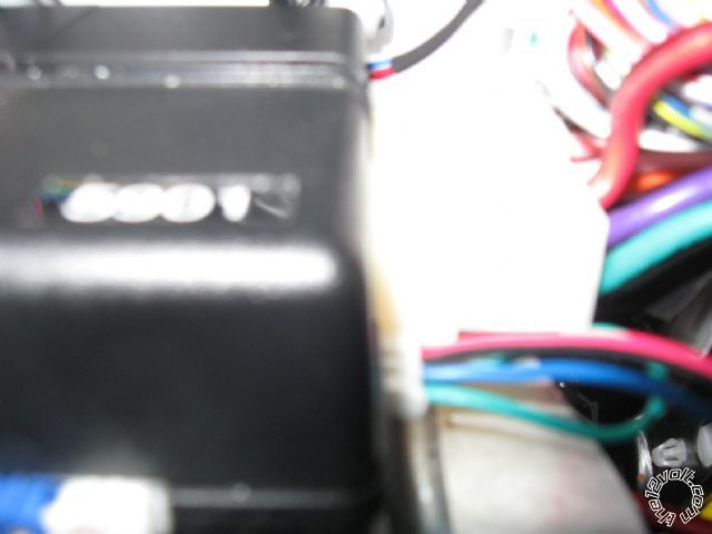
I am upgrading a 5901 ( from eBay 9/2009 ) . Adding 500t , 504d & 506t .

I include a picture of a 4 pins , on same side and next to H1 connector ( big starter wires ) . Is this that 4pins , the correct MUX port ?

Directed Quick Reference Wiring Guide ( QR5702 2008-08 )  does not show MUX port .

Thank You ...                                             rcavictor .

Thanks for answering, rcavictor.              
fredddy9 
Member - Posts: 40
Member spacespace
Joined: October 21, 2009
Location: Alberta, Austria
Posted: September 03, 2010 at 9:09 AM / IP Logged  
rcavictor, looks like you bought previous Viper 5901 brain unit. My MUX port location is exactly as described on the diagram i posted on the top of this page.
From your picture is seems like you plugged your sensor connector correctly, green and blue wires are alarm warn away inputs.
Just bear in mind that MUX port provides constant power supply, so your sensor will draw current even when car is not armed.
Here is my setup if its helpful, you actually don't need to separate MUX port inputs with diodes like i did. only if you connecto two or more sensors to one MUX input.
mux port on a 5901 -- posted image.
fredddy9 
Member - Posts: 40
Member spacespace
Joined: October 21, 2009
Location: Alberta, Austria
Posted: September 03, 2010 at 9:57 AM / IP Logged  
Ok, never mind about diagram of my newer Viper 5901 which has a separate dedicated MUX port.
Your older 5901 brain_unit must be this one:
mux port on a 5901 -- posted image.  
And i don't know whether that D2D port (next to H1) can be used as MUX port or not. Maybe some other users will unveil this mystery.
rcavictor 
Member - Posts: 35
Member spacespace
Joined: January 26, 2010
Location: Quebec, Canada
Posted: September 03, 2010 at 10:02 AM / IP Logged  

Hello 12Volts friends ,

- So it is a Viper 5901 brain unit previous issue .

- Is this MUX port ( previous Viper 5901 brain unit ) to the right of 5901 marking , near H1 ( big starter wire port ) ?

Thank You ...                                                     rcavictor .

Thanks for answering, rcavictor.              
rcavictor 
Member - Posts: 35
Member spacespace
Joined: January 26, 2010
Location: Quebec, Canada
Posted: September 03, 2010 at 10:16 AM / IP Logged  

Hello 12Volts friends ,

Big starter wire port is H3 ...

Thank  You ...                        rcavictor .

Thanks for answering, rcavictor.              
rcavictor 
Member - Posts: 35
Member spacespace
Joined: January 26, 2010
Location: Quebec, Canada
Posted: September 03, 2010 at 10:25 AM / IP Logged  

Hello 12Volts friends ,

So , if my 5901 does not have any MUX port , I must use H1 blue trunk (-) instant trigger output to my 3 sensor blue wires ... including diodes ...

Thank  You ...                                                   rcavictor  .

Thanks for answering, rcavictor.              
howie ll 
Pot Metal - Posts: 16,466
Pot Metal spacespace
Joined: January 09, 2007
Location: United Kingdom
Posted: September 03, 2010 at 1:49 PM / IP Logged  
Yes including diodes BUT you are going to regret all those sensors giving you false alarms unless you spend hours CAREFULLY setting each one up beforehand.
Frankly all you need is a 508d.
rcavictor 
Member - Posts: 35
Member spacespace
Joined: January 26, 2010
Location: Quebec, Canada
Posted: September 03, 2010 at 2:15 PM / IP Logged  

Hello 12Volts friends ,

Nervertheless , the following is written in the Directed Electronics N5702V 2008-08 Inst... Guide  ( page 28 )included in the box .

Optional sensor port - 4-pin connector

There is a shock sensor built onboard the main unit. This connector is an optional

sensor port to add sensors to the security system. Optional sensors that may be

used are: 508D Doubleguard Proximity Field Disturbance, 509U Ultrasonic

Sensor, 506T Glass Break Sensor, and 507M Digital Tilt Sensor.

This input can also be used for a second 504D Doubleguard Shock Sensor, or

for additional pin and magnetic switches.

Any idea ...

Thanks for answering, rcavictor.              
rcavictor 
Member - Posts: 35
Member spacespace
Joined: January 26, 2010
Location: Quebec, Canada
Posted: September 03, 2010 at 4:26 PM / IP Logged  

Hello 12Volts friends ,

By now I have tested this 4 pin port (optional sensor port - 4-pin connector) with 506t wiring . Red is 12 volts from 5901 , black is ground ,  blue is (-) alarm trigger ( short ground touch = warning , long touch = alarm ) .

Multitester confirms this 4 pins does like a MUX ...

Thanks for answering, rcavictor.              
fredddy9 
Member - Posts: 40
Member spacespace
Joined: October 21, 2009
Location: Alberta, Austria
Posted: September 04, 2010 at 1:02 AM / IP Logged  
Thats how i found about my MUX port too, i had to test it myself because i couln't get any answer on the net.
Regarding different sensors what you've been asking, i'd only go with field disturbance sensor and maybe tilt sensor (which i'm planning to add in the future).
As i shown in my diagram i hooked up two disturbance sensors, they work great but when its raining i get many false alarms, but its not a problem to bypass them with a remote   2x F & close   or 3x F & close (we'll still get warnings at the remote).
triggering either of two MUX inputs will report Sensor 2 zone 4, i haven't found any difference between them.
And i only connected short 300ms signals from my field disturbance sensors so they can only trigger 'warn away' not full trigger for example from rain.
I don't know about DEI508d , i'm using some aftermarket sensors but I've noticed that the more humid weather the more sensitive is the detection, and the more dry and hot its less sensitive. So its important to install the sensor in a place where you can easily reach and readjust.
There are two adjusting screws, my instruction says its for Zone 1 (range ~2m) and Zone 2 (~1m), but i found out that Screw_1 adjusts the range of both zones, while the other makes them more or less sensitive.
Page of 2

  Printable version Printable version Post ReplyPost New Topic
You cannot post new topics in this forum
You cannot reply to topics in this forum
You cannot delete your posts in this forum
You cannot edit your posts in this forum
You cannot create polls in this forum
You cannot vote in polls in this forum

  •  
Search the12volt.com
Follow the12volt.com Follow the12volt.com on Facebook
Saturday, May 4, 2024 • Copyright © 1999-2024 the12volt.com, All Rights Reserved Privacy Policy & Use of Cookies
Disclaimer: *All information on this site ( the12volt.com ) is provided "as is" without any warranty of any kind, either expressed or implied, including but not limited to fitness for a particular use. Any user assumes the entire risk as to the accuracy and use of this information. Please verify all wire colors and diagrams before applying any information.

Secured by Sectigo
the12volt.com spacer
Support the12volt.com
Top
the12volt.com spacer