the12volt.com spacer
icon

unlock all doors w/1 press on oem remote


Post ReplyPost New Topic
< Prev Topic Next Topic >
wts99 
Member - Posts: 3
Member spacespace
Joined: July 14, 2005
Posted: November 16, 2010 at 7:03 PM / IP Logged  
I'm not 100% positive and figured someone on here smarter than I could answer this.
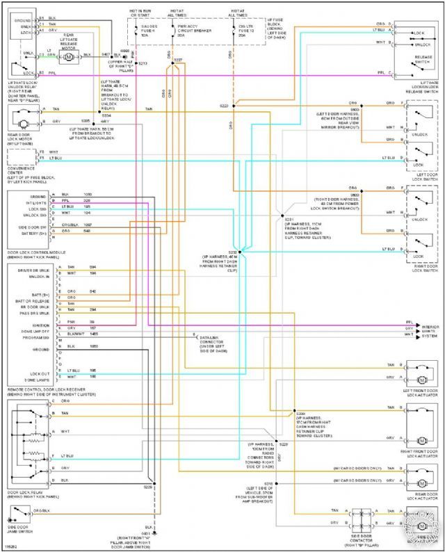
I have a 1999 Chevy Astro van that is designed to unlock only the drivers door on the first press of the factory key-less entry, and the rest of the doors on the seconds press. Unlike other vehicles where this is a programmable option, it is not on this vehicle. The 'remote control door lock receiver' is the only thing that controls the drivers side door lock actuator.
I feel that I have found the solution following the wiring diagram that I got from another website. If I insert a timed relay activated by pin A(tan) that controls pin B(white) on the 'remote control door lock receiver', it should just allow a short pulse to pin B(white) on the receiver instead of creating an 'unlock loop' where it would keep constantly keep trying to unlock the doors. Because putting 12volts to pin B(white) will cause pin A to supply 12volts to the timed relay and the drivers door lock again.
Does this sound correct, and would something like DEI 528T Pulse Timer Relay Module work for this application? Or is there a better/cheaper way of doing this?
I wasn't sure if this should be in this forum or the relay forum but figured this to be a little more in depth.
unlock all doors w/1 press on oem remote -- posted image.
wts99 
Member - Posts: 3
Member spacespace
Joined: July 14, 2005
Posted: November 30, 2010 at 1:22 PM / IP Logged  
If this belongs in the relay forum, could an admin move it?
Ween 
Platinum - Posts: 1,366
Platinum spacespace
Joined: August 01, 2004
Location: Illinois, United States
Posted: November 30, 2010 at 1:56 PM / IP Logged  

hi,

you'll need a relay (SPST or SPDT) ..Bosch type is fine.  connect as follows:

term 86 to drivers door unlock wire (tan),

term 85 to ground (black),

term 30 to drivers door unlock wire (tan),

term 87 to unlock wire (white).

when drivers door unlock wire has positive voltage on it, it will trigger unlock relay coil, thus unlocking all other doors.

91stt 
Silver - Posts: 564
Silver spaceThis member consistently provides reliable informationspace
Joined: May 24, 2006
Location: New Jersey, United States
Posted: November 30, 2010 at 4:36 PM / IP Logged  
You should be able to do it with just a diode. Placing a diode between pins A (tan) & B (white) at the door lock receiver with the band towards pin B. When the driver door unlock wire activates via remote, a +12v pulse will be sent to the d/l relay and unlock all of the doors.
This information is provided only as a reference.
All circuits should be verified with a digital multi-meter prior to making any connections.
wts99 
Member - Posts: 3
Member spacespace
Joined: July 14, 2005
Posted: December 02, 2010 at 1:19 AM / IP Logged  
Thanks for the replies! As long as B (white) has +12 on it, it continues to supply +12v to A (tan).
1st Button press gives +12v to A(tan).
2nd Button press gives +12v to A(tan), G(tan), and H(tan)
If the remote is pressed and A supplies B with 12v it will continue to supply A with 12v creating a loop.
A should give B 12v but only for a fraction of a second, regardless of how long A is energized. How do I do that?
91stt 
Silver - Posts: 564
Silver spaceThis member consistently provides reliable informationspace
Joined: May 24, 2006
Location: New Jersey, United States
Posted: December 02, 2010 at 12:05 PM / IP Logged  
If it is locking up as you describe than you will need a relay.
Cut the white wire and connect the relay as follows:
86 = Pin A (tan)
85 = chassis ground
30 = d/l relay side of white wire
87a = remote control d/l receiver side of white wire
87 = constant 12V (fused at 10A)
This information is provided only as a reference.
All circuits should be verified with a digital multi-meter prior to making any connections.

Sorry, you can NOT post a reply.
This topic is closed.

  Printable version Printable version Post ReplyPost New Topic
You cannot post new topics in this forum
You cannot reply to topics in this forum
You cannot delete your posts in this forum
You cannot edit your posts in this forum
You cannot create polls in this forum
You cannot vote in polls in this forum

  •  
Search the12volt.com
Follow the12volt.com Follow the12volt.com on Facebook
Thursday, May 2, 2024 • Copyright © 1999-2024 the12volt.com, All Rights Reserved Privacy Policy & Use of Cookies
Disclaimer: *All information on this site ( the12volt.com ) is provided "as is" without any warranty of any kind, either expressed or implied, including but not limited to fitness for a particular use. Any user assumes the entire risk as to the accuracy and use of this information. Please verify all wire colors and diagrams before applying any information.

Secured by Sectigo
the12volt.com spacer
Support the12volt.com
Top
the12volt.com spacer