the12volt.com spacer
icon

2005 nissan titan, alarm/remote start


Post ReplyPost New Topic
< Prev Topic Next Topic >
dougielv 
Member - Posts: 8
Member spacespace
Joined: December 17, 2010
Location: Nevada, United States
Posted: December 17, 2010 at 12:18 PM / IP Logged  

I connected the alarm (brown 12v +) to the RED / black wire on the brake swich.every time i press the brake pedal the doors lock.This only happens when the blower motor ir turned on.And on the tach wire you can use any wire except WHITE/ blue or black???? thank you

tonanzith 
Gold - Posts: 593
Gold spaceThis member consistently provides reliable informationspace
Joined: July 18, 2008
Location: Washington, United States
Posted: December 18, 2010 at 11:11 PM / IP Logged  
What alarm are you using?
Gary Sather
dougielv 
Member - Posts: 8
Member spacespace
Joined: December 17, 2010
Location: Nevada, United States
Posted: December 28, 2010 at 11:21 PM / IP Logged  
It is a performance teknique icbm-7071
dougielv 
Member - Posts: 8
Member spacespace
Joined: December 17, 2010
Location: Nevada, United States
Posted: June 05, 2011 at 9:28 PM / IP Logged  
Does anyone know if I should isolate the brake wire input switch via relay?The problem is every time I depress the brake pedal (while the a/c is on)the doors lock???
dougielv 
Member - Posts: 8
Member spacespace
Joined: December 17, 2010
Location: Nevada, United States
Posted: June 13, 2011 at 4:38 PM / IP Logged  
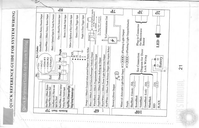
I have a 2005 Nissan Titan,finally got all bugs worked out..Last thing is remote start.The engine does crank but not start..That the instructions for my model.I have connected,read to green(12v constant)orange to red (acc wire)pink to brown(starter wire) pink to lt green( 2nd ignition wire)purple to BLACK/ red (ignition wire)I also have an omega imo 520 interface connected,any help would be appreciated.
2005 nissan titan, alarm/remote start -- posted image.
kreg357 
Platinum - Posts: 7,783
Platinum spaceThis member has made a donation to the12volt.com. Click here for more info.spaceThis member has been recognized as an authority in Electrical Theory. Click here for more info.spaceThis member has been recognized as an authority in Mobile Security and Convenience. Click here for more info.spacespace
Joined: January 30, 2009
Location: Pennsylvania, United States
Posted: June 13, 2011 at 5:37 PM / IP Logged  

Are you running W2W from the remote starter to the IMO-520?  I am not familiar with your remote start unit.  According to DEI, the

RF bypass section only works in D2D mode.  Not sure on this because I have never used an XK520 / IMO-520

2005 Nissan Titan: XK520 - NISSDL 3.02

 W2W

AV-Domelight Activation
DL-Arm Factory Security
DL-Disarm Factory Security
DL-Door Lock Control
DL-Door Unlock
DL-Trunk / Hatch Release

 D2D

AV-Domelight Activation
DL-Arm Factory Security
DL-Disarm Factory Security
DL-Door Lock Control
DL-Door Unlock
DL-Trunk / Hatch Release
FOB-Control of aftermarket alarm with OEM remote
PK-Universal RF Bypass- Key Req'd
SS-CAN Alarm control w/ FOB remote
ST-Door Lock Status

As for your ignition wiring, looks like you will need some relays.

Bulldog lists two Starter wires that must be powered.  They also list two ACC wires and only one IGN.

 12 VOLT CONSTANT                            GREEN (+)                                                                                     IGNITION SWITCH HARNESS 
 STARTER                                                 BROWN (+)                         See NOTE *1                                  IGNITION SWITCH HARNESS 
 STARTER 2                                              LIGHT GREEN (+) or BLUE/GREEN (+) See NOTE *1        IGNITION SWITCH HARNESS
 IGNITION 1                                               BLACK/ RED (+)                                                                           IGNITION SWITCH HARNESS
 ACCESSORY /HEATER BLOWER 1     RED (+)                                                                                        IGNITION SWITCH HARNESS 
 ACCESSORY /HEATER BLOWER 2     PURPLE (+)                                                                                IGNITION SWITCH HARNESS
NOTE *1 When Installing a REMOTE STARTER, you MUST use BOTH Starter #1 and Starter #2 wires. Both wires must be
                 connected to the STARTER/CRANKING Output wire from the Remote Starter or the vehcile will NOT Remote Start
                 when the Engine is cold.

DEI has the same info:

12volts                           green (40A)  +                            ignition switch, white 6 pin plug, pin 3
Starter                            brown  +                                      ignition switch, white 6 pin plug, pin 2
Second Starter             lt. green or blue/green  +         ignition switch, white 6 pin plug, pin 6
Ignition                          BLACK/ red  +                                 ignition switch, white 6 pin plug, pin 1
Accessory                     red  +                                           ignition switch, white 6 pin plug, pin 4
Second Accessory      purple  +                                     ignition switch, white 6 pin plug, pin 5

Soldering is fun!
dougielv 
Member - Posts: 8
Member spacespace
Joined: December 17, 2010
Location: Nevada, United States
Posted: June 20, 2011 at 1:30 PM / IP Logged  
I believe it is w2w,but i will check,thank you

Sorry, you can NOT post a reply.
This topic is closed.

  Printable version Printable version Post ReplyPost New Topic
You cannot post new topics in this forum
You cannot reply to topics in this forum
You cannot delete your posts in this forum
You cannot edit your posts in this forum
You cannot create polls in this forum
You cannot vote in polls in this forum

  •  
Search the12volt.com
Follow the12volt.com Follow the12volt.com on Facebook
Wednesday, May 8, 2024 • Copyright © 1999-2024 the12volt.com, All Rights Reserved Privacy Policy & Use of Cookies
Disclaimer: *All information on this site ( the12volt.com ) is provided "as is" without any warranty of any kind, either expressed or implied, including but not limited to fitness for a particular use. Any user assumes the entire risk as to the accuracy and use of this information. Please verify all wire colors and diagrams before applying any information.

Secured by Sectigo
the12volt.com spacer
Support the12volt.com
Top
the12volt.com spacer