the12volt.com spacer
icon

advanced circuit


Post ReplyPost New Topic
< Prev Topic Next Topic >
xrw50 
Member - Posts: 10
Member spacespace
Joined: January 16, 2011
Posted: June 23, 2011 at 1:44 AM / IP Logged  
(First off i would like to thank this website for teaching me what i know about the electrical systems of cars.)
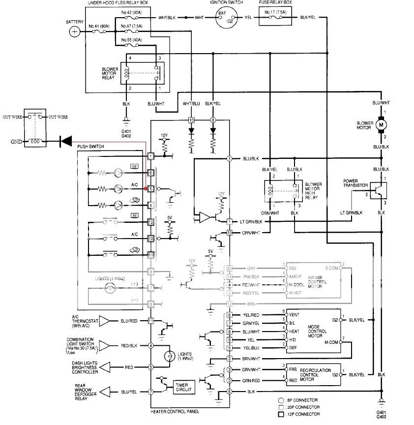
I am trying to install an advanced but still convenient kill switch in my 1999 Honda Civic base model. The goal is to make a starter kill using the stock AC button (my car does not have AC). Theres an LED on the button that lights up when the button is pushed so i figured the kill switch would be disarmed only when the LED is on.
So here is the circuit im working on and what i did:
advanced circuit -- posted image.
(red wire signifies my modification)
Because of my limited knowledge with circuits, i cannot really understand why it doesnt work. When i pulled out the multimeter to diagnose the problem, i got some interesting results:
  • Before i tapped into the wire, it was outputting 12v when LED was off and .05v when LED was on
  • After i tapped it, LED remained constantly on and was outputting 1.3V
  • Just for kicks i tested for continuity between the wire and ground and the LED turned on but was very dim and the multimeter read approx. 500ohms
I dont know why the LED on the switch turns on randomly and i dont really understand the circuit diagram. So my question is, is it even possible to make my idea work. If so, how can i do it??
oldspark 
Gold - Posts: 4,913
Gold spacespace
Joined: November 03, 2008
Location: Australia
Posted: June 23, 2011 at 4:23 AM / IP Logged  
That LED circuit is a grounding circuit.
Your relay coil (like the LED) should be hot (+12V) and it is then grounded when the LED comes on. The diode also has to be reverse, though since it isn't necessary, I'd put it across the coil to suppress spikes - ie, line end to +12V.
But if that grounding transistor cannot handle the coil current, it will blow. (The LED is maybe ~20mA; the relay coil may be 250mA - ie. 14V/<coil resistance in Ohms>.)
It's also not a good idea to cut wires. A better scheme is usually to ground ignitor outputs or other grounded sensors that are required for engine starting or running. (IE - the NC relay contact shorts to ground any sensor signal or the ignitor/points output to the ignition coil(s).)
xrw50 
Member - Posts: 10
Member spacespace
Joined: January 16, 2011
Posted: June 23, 2011 at 12:54 PM / IP Logged  
Ahh yes now that you point it out it makes so much sense! For some reason i was stuck on the idea that it was outputting voltage. Hopefully the transistor can handle the coil. Thank you!

Sorry, you can NOT post a reply.
This topic is closed.

  Printable version Printable version Post ReplyPost New Topic
You cannot post new topics in this forum
You cannot reply to topics in this forum
You cannot delete your posts in this forum
You cannot edit your posts in this forum
You cannot create polls in this forum
You cannot vote in polls in this forum

  •  
Search the12volt.com
Follow the12volt.com Follow the12volt.com on Facebook
Friday, May 3, 2024 • Copyright © 1999-2024 the12volt.com, All Rights Reserved Privacy Policy & Use of Cookies
Disclaimer: *All information on this site ( the12volt.com ) is provided "as is" without any warranty of any kind, either expressed or implied, including but not limited to fitness for a particular use. Any user assumes the entire risk as to the accuracy and use of this information. Please verify all wire colors and diagrams before applying any information.

Secured by Sectigo
the12volt.com spacer
Support the12volt.com
Top
the12volt.com spacer