the12volt.com spacer
icon

viper 5901 in a supra


Post ReplyPost New Topic
< Prev Topic Next Topic >
ask92 
Member - Posts: 34
Member spacespace
Joined: August 08, 2011
Posted: August 08, 2011 at 10:20 PM / IP Logged  
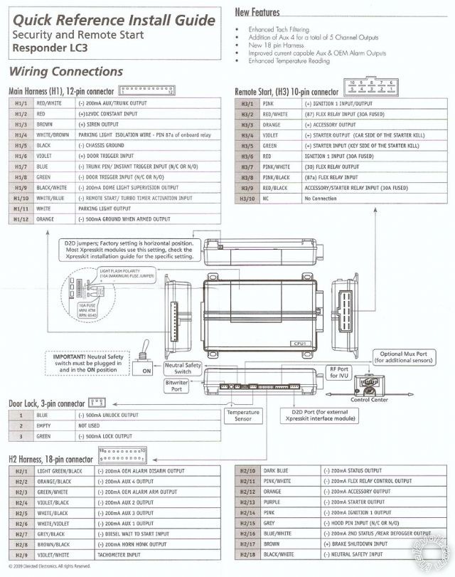
I am installing a viper 5901 remote start into my 1989 turbo targa supra with a manual tranny. I need some help figuring out where some of the wires connect.
These are the wires i am unsure of how to connect:
-WHITE/ Brown Flex parking light relay 87A
-Violet starter output (car side of starter wire)..[I'm guessing this is the wire between the starter and fuse box?]
-WHITE/ Blue remote start activation (-) input
-Light GREEN/ Black OEM disarm (-) 200mA output
-Light GREEN/ White OEM arm (-) 200mA output
-Orange ground-when-armed (-) 500mA output (just go to ground?)
Diagram:
viper 5901 in a supra -- posted image.
Any help is appreciated and yes i have seen the supra wiring info on this site, and all this info is not on it. Thank you for your help.
-Andrew
howie ll 
Pot Metal - Posts: 16,466
Pot Metal spacespace
Joined: January 09, 2007
Location: United Kingdom
Posted: August 09, 2011 at 12:36 AM / IP Logged  
Having seen your comments, I'd strongly advise you not to proceed on your own. Or at least read the instructions again. Having said that:-
Cut the wire which goes to live on cranking at the ignition switch loom.
Key side to H/3 5 GREEN.
Starter side to H/3 4 VIOLET.
Ignore the rest as in don't connect and read the instructions again.
ask92 
Member - Posts: 34
Member spacespace
Joined: August 08, 2011
Posted: August 09, 2011 at 1:11 AM / IP Logged  
What instructions? The only thing provided was eh wiring diagram. I am very very car savy, i just installed the supras engine myself. Its just the wording in the diagram i am unsure about.
howie ll 
Pot Metal - Posts: 16,466
Pot Metal spacespace
Joined: January 09, 2007
Location: United Kingdom
Posted: August 09, 2011 at 3:23 AM / IP Logged  
I don't think so, stop guessing and get out a DMM and test your car's wiring. Locks will be in the driver's kick panel, tach behind the instrument panel or the coil (terminal 15 or -) if there's a single coil. Door trigger will be at the driver's kick panel, probably RED / white with silver dots, indicators or lights at the ignition switch loom along with ign, ACC and possibly second starter wire TEST. BLACK/ white wire from Viper to parking brake switch. There that's all from memory and I haven't worked on one for about 20 years. That's savvy.
smokeman1 
Platinum - Posts: 1,588
Platinum spaceThis member has made a donation to the12volt.com. Click here for more info.spaceThis member has been recognized as an authority in Mobile Security and Convenience. Click here for more info.spacespace
Joined: September 14, 2009
Location: Wisconsin, United States
Posted: August 09, 2011 at 6:19 AM / IP Logged  

Go to the downloads section of this site and download the install manual for the Viper 5701. It will explain each wires use. It may not have a 18 pin connector (H2 Harness), but you should be able to match up the three harness from the 5701 that make up the newer 18 pin.

When all else fails, Read the Instructions
Support the12volt.com Make a Donation
ask92 
Member - Posts: 34
Member spacespace
Joined: August 08, 2011
Posted: August 09, 2011 at 8:17 PM / IP Logged  
All the tings you just mentioned i already i have done. And non of them were on my list. I only need help on the wires listed in my previous post.
t&t tech 
Platinum - Posts: 2,608
Platinum spacespace
Joined: October 05, 2008
Location: Trinidad and Tobago
Posted: August 09, 2011 at 8:38 PM / IP Logged  
The only wire you're using from the ones you listed would be the violet wire, you need to cut the true starter wire and connect the heavy green to the side from the key and the violet to the other side.
commit your way to jehovah and he will act in your behalf. psalms 37:5

Sorry, you can NOT post a reply.
This topic is closed.

  Printable version Printable version Post ReplyPost New Topic
You cannot post new topics in this forum
You cannot reply to topics in this forum
You cannot delete your posts in this forum
You cannot edit your posts in this forum
You cannot create polls in this forum
You cannot vote in polls in this forum

  •  
Search the12volt.com
Follow the12volt.com Follow the12volt.com on Facebook
Friday, May 3, 2024 • Copyright © 1999-2024 the12volt.com, All Rights Reserved Privacy Policy & Use of Cookies
Disclaimer: *All information on this site ( the12volt.com ) is provided "as is" without any warranty of any kind, either expressed or implied, including but not limited to fitness for a particular use. Any user assumes the entire risk as to the accuracy and use of this information. Please verify all wire colors and diagrams before applying any information.

Secured by Sectigo
the12volt.com spacer
Support the12volt.com
Top
the12volt.com spacer