the12volt.com spacer
icon

wire keyless entry system for other use


Post ReplyPost New Topic
< Prev Topic Next Topic >
stone68 
Member - Posts: 6
Member spacespace
Joined: October 19, 2011
Location: Nevada, United States
Posted: October 19, 2011 at 11:53 AM / IP Logged  
Hello all- am new here but have found many topics in the forums very helpful.
I'm on a quest to utilize a wireless system (i presume this should be a keyless entry) to activate a servo for movement one way (fwd) then the other way (reverse) on a 12v system. Most common servos operate 4.8-6V and must be modified to move the 180 degrees i'm looking for. So far I'm using a DPDT 6 pole switch to reverse polarity and also using a small LED switch to activate when servo is in a certain position- and I've incorporated a 5W 33ohm resistor (to bring the volts down?). This all works fine WIRED.
So i purchased some basic AutoPage alarm and tinkered a bit until i found that i could wire my 2 servo wires to it (to it's pulse generating two output wires), ground and power it, and MUALA - push the remote lock button and servo moved one way-pushed other remote unlock button and servo moved the other way. It worked!!!!~ Problem is that this alarm system is way more sophisticated than i need (motion detection, multiple door wiring, trunk, lights, siren, etc + both remotes come with like 5 buttons. I found it pushes like 9V but in a quick burst to my servo- seems to work. I tested it with the resistor in line and it worked just fine- a little slower, but fine.
I bought an off-brand chinese 'keyless entry' kit. Im obviously not knowledgable in this field of electronics--- but i cannot seem to get this to work- i can get no real detectable power coming from any leads, and one remote just doesn't even seem to do anything... the other makes it click.
I'm writing for help- perhaps a cheap product recommendation (simple and with remotes that only have two buttons) and/or some help in wiring considerations.
Thanks very much for reading and i look forward to any input.
stone
i am an idiot 
Platinum - Posts: 13,670
Platinum spaceThis member consistently provides reliable informationspace
Joined: September 21, 2006
Location: Louisiana, United States
Posted: October 19, 2011 at 1:41 PM / IP Logged  

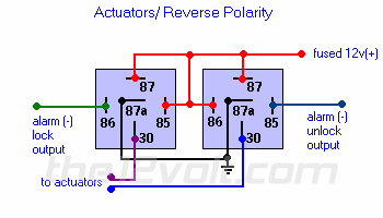
Chances are the keyless module you purchased has only a negative output for the door lock system.  You will have to use 2 relays in order to get what you are after.

Actuators / Reverse Polarity
This is practically identical to the 5 wire alternating 12V(+) system above. The only difference is there's no switch! Both motor legs rest at ground at the relays. To lock or unlock the vehicle, polarity is changed on one motor leg.
wire keyless entry system for other use -- posted image.

stone68 
Member - Posts: 6
Member spacespace
Joined: October 19, 2011
Location: Nevada, United States
Posted: October 19, 2011 at 2:05 PM / IP Logged  
thank you but i went through all that and to no avail. i put voltmeter on all leads coming from the system and only got like a .4 of one volt to pop only under like two scenarios while pushing the remote, and with the two relays as you mentioned i got same or less going out to my servo. I'm thinking the system was bad.... but thank you.
stone
i am an idiot 
Platinum - Posts: 13,670
Platinum spaceThis member consistently provides reliable informationspace
Joined: September 21, 2006
Location: Louisiana, United States
Posted: October 19, 2011 at 3:56 PM / IP Logged  
Red meter lead on a positive 12 volt source. Black meter lead on the unlock wire of the keyless entry module. Press lock or unlock and notice the voltage. Then black lead to the lock wire of the keyless module. Lock and unlock it and notice the voltage.
stone68 
Member - Posts: 6
Member spacespace
Joined: October 19, 2011
Location: Nevada, United States
Posted: October 19, 2011 at 11:01 PM / IP Logged  
just tried that- no changes to report- no readings. this generic entry system does have some trunk/door side pins on it that have jumpers- the one on the right has two sets of pins and the one on the left has one set- on the left the lower pin reads 4.97 at all times. On the right the upper outer one reads 12.97 at all times. No changes on any readings when remote buttons are pressed...... aaaahhhahharrraggghhh
stone
howie ll 
Pot Metal - Posts: 16,466
Pot Metal spacespace
Joined: January 09, 2007
Location: United Kingdom
Posted: October 20, 2011 at 1:58 AM / IP Logged  
I think the answer is the following:-
Most keyless entry systems from "reputable companies" such as Compustar, DEI, Audiovox group, Autopage etc. have basic K/E systems with relay driven outputs, look in the specs. or "6 wire lock output" with these you can replace the switch (or even leave it in) using "add actuator" or "5 wire switch" methods, i.e. splice into the motor leads.
As in other walks of life you get what you pay for.
Avoid anything with vague or "Chinglish" instructions.
howie ll 
Pot Metal - Posts: 16,466
Pot Metal spacespace
Joined: January 09, 2007
Location: United Kingdom
Posted: October 20, 2011 at 2:01 AM / IP Logged  
The cost factor is that the above systems tend to be identical to some of the alarms without a siren and sensor, hence the cost.
howie ll 
Pot Metal - Posts: 16,466
Pot Metal spacespace
Joined: January 09, 2007
Location: United Kingdom
Posted: October 20, 2011 at 5:35 AM / IP Logged  
Viper 211HV.
stone68 
Member - Posts: 6
Member spacespace
Joined: October 19, 2011
Location: Nevada, United States
Posted: October 20, 2011 at 12:23 PM / IP Logged  
Hello- I am using a keyless entry system to actuate a servo one direction or the other based on remote button pushes. After some trial and error I do have this system working and am fairly happy. These servos are only 4.8-6V and I'm running all this on 12V. The servos are modified so that I'm only using the motor, gears, and casing, and not utilizing servo's pulse capabilities... That being said, the servo motors can and do seem to take the full 12V even if it's only a quick little pulse from the keyless entry system, however, the motor moving faster at 12V just tears up all the gears and destroys the modified servo...
I had been using a 5 watt 33 ohm resistor on my lead coming from the + battery BEFORE the keyless entry system. The 5 watt 33 ohm is what I was told by a source.. Is this correct? And, would I be better off putting TWO of those resistors on my TWO servo leads- one on each side? and Leaving the + lead from the battery to the keyless system alone at full 12V. Which is better?
thx much
stone
stone68 
Member - Posts: 6
Member spacespace
Joined: October 19, 2011
Location: Nevada, United States
Posted: October 20, 2011 at 4:04 PM / IP Logged  
Hello- I am using a keyless entry system to actuate a servo one direction or the other based on remote button pushes. After some trial and error I do have this system working and am fairly happy. These servos are only 4.8-6V and I'm running all this on 12V. The servos are modified so that I'm only using the motor, gears, and casing, and not utilizing servo's pulse capabilities... That being said, the servo motors can and do seem to take the full 12V even if it's only a quick little pulse from the keyless entry system, however, the motor moving faster at 12V just tears up all the gears and destroys the modified servo...
I had been using a 5 watt 33 ohm resistor on my lead coming from the + battery BEFORE the keyless entry system. The 5 watt 33 ohm is what I was told by a source.. Is this correct? And, would I be better off putting TWO of those resistors on my TWO servo leads- one on each side? and Leaving the + lead from the battery to the keyless system alone at full 12V. Which is better?
thx much
stone
Page of 2

  Printable version Printable version Post ReplyPost New Topic
You cannot post new topics in this forum
You cannot reply to topics in this forum
You cannot delete your posts in this forum
You cannot edit your posts in this forum
You cannot create polls in this forum
You cannot vote in polls in this forum

  •  
Search the12volt.com
Follow the12volt.com Follow the12volt.com on Facebook
Saturday, May 4, 2024 • Copyright © 1999-2024 the12volt.com, All Rights Reserved Privacy Policy & Use of Cookies
Disclaimer: *All information on this site ( the12volt.com ) is provided "as is" without any warranty of any kind, either expressed or implied, including but not limited to fitness for a particular use. Any user assumes the entire risk as to the accuracy and use of this information. Please verify all wire colors and diagrams before applying any information.

Secured by Sectigo
the12volt.com spacer
Support the12volt.com
Top
the12volt.com spacer