the12volt.com spacer
icon

2004 hyundai elantra starter interrupt


Post ReplyPost New Topic
< Prev Topic Next Topic >
rabeatz 
Member - Posts: 4
Member spacespace
Joined: January 13, 2012
Location: Florida, United States
Posted: January 13, 2012 at 12:43 PM / IP Logged  
I installed a Galaxy G20 Alarm in my 2004 Hyundai Elantra - ( manual available here - http://www.scytek.net/manuals/galaxy/g20.pdf) . However, I am having trouble getting the starter interrupt relay to work properly.
Here is the wiring info available on your website - https://www.the12volt.com/installbay/forum_posts.asp~TID~52899
Here is the diagram included with the manual -
2004 hyundai elantra starter interrupt -- posted image.
This is the overall wiring diagram for the unit.
2004 hyundai elantra starter interrupt -- posted image.
The manual doesn't specify what type of relay I should be using, so perhaps that is my problem - should it be a SPST with dual outputs? or a SPDT? I believe I am connecting it properly, however when I wire it up, I get no starting capabilities at all.
I'm a little confused on some of the connections I need to make, so perhaps that is my problem.
The yellow, orange, and violet/purple wires mentioned in the starter interrupt relay diagram, I have not connected to anything other than directly to the relay and to the control unit. Is the yellow wire supposed to be going to the + on my ignition as well? Should I be grounding the orange wire? I haven't done either because I don't want to damage the unit.
I have connected the wires exactly as they appear on the diagram for the starter and it never starts. The relay I have is a SPST. If my understanding is correct, shouldn't there be a voltage between the Yellow and Orange wires (86 and 85) when the alarm is disarmed? I removed them from the relay and just hooked them up to the multimeter and I didn't see any voltage activity when arming or disarming the alarm. It just seems like there is nothing going through 85 and 86 so it's not actually activating the relay.
Can anyone give me some hints or tips on what I should be doing, or something I can check?
rabeatz 
Member - Posts: 4
Member spacespace
Joined: January 13, 2012
Location: Florida, United States
Posted: January 13, 2012 at 1:03 PM / IP Logged  
Looking at the diagram again, I'm noticing that the orange is ground when ARMED. So that means I should be using a SPDT relay.. right? I think that may be the problem all along. The diagram looks like it's a normally open circuit.
If anyone could confirm that this sounds correct, I'd appreciate it!
shortcircuit161 
Silver - Posts: 556
Silver spaceThis member has made a donation to the12volt.com. Click here for more info.spacespace
Joined: August 29, 2010
Location: United States
Posted: January 13, 2012 at 1:07 PM / IP Logged  
You would use a standard Bosch type 30/40 amp SPDT relay.
2004 hyundai elantra starter interrupt -- posted image.
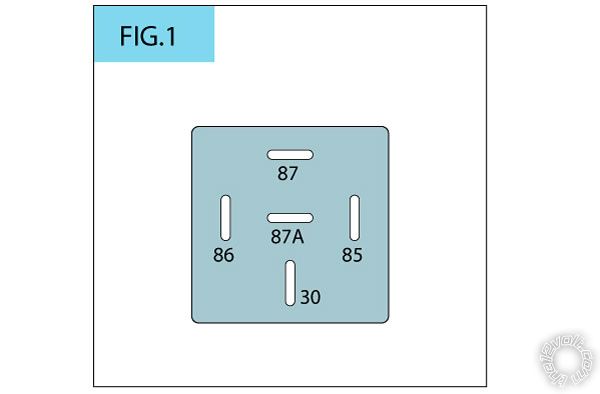
You would connect one side of the starter wire to pin 87a in the center of the relay and the other side of the starter wire to pin 30 (common) on the bottom of the relay. That's a N.C.(Normally Closed) connection that will allow you to start it with your key at any time. When the alarm is armed, the orange (Ground When Armed) wire will engage the relay and break the connection across the starter wire, preventing it from starting.
Pins 85 and 86 would have 12v constant on one side (usually pin 85) and the Ground when armed orange wire to the other side (usually pin 86).
Hope that helps!!
offroadzj 
Gold - Posts: 2,043
Gold spaceThis member has made a donation to the12volt.com. Click here for more info.spaceThis member has been recognized as an authority in Mobile Security and Convenience. Click here for more info.spacespace
Joined: June 03, 2005
Location: New York, United States
Posted: January 13, 2012 at 1:08 PM / IP Logged  
All of the ignition and accessory wires must be connected as normal. Then you will want to run an ignition line (new wire) from the ignition wire to Pin 85. Then run your starter interrupt wire to Pin 86 of the relay. Cut your factory starter wire and connect the key side of the cut wire to pin 87a of the relay and the car side of the cut starter wire as well as the violet (+) starter output of the remote start to Pin 30 of the relay. The relay MUST be a 5 pin relay since Pin 87a does not exist on a 4 pin relay.
What exactly is happening when you try to remote start it with the relay connected?
I'm not familiar with that unit but if it is not an alarm, and you are confident that you will not turn the key to the start position after the vehicle is remote started then I wouldn't even bother with the starter interrupt.
Kenny
Owner / Technician
KKD Garage LLC
Albany, NY 12205
rabeatz 
Member - Posts: 4
Member spacespace
Joined: January 13, 2012
Location: Florida, United States
Posted: January 13, 2012 at 1:16 PM / IP Logged  
Discount auto parts and autozone only had 1 (each place) in the way of relays - one had a 4 Pin SPST and the other had a 5 PIN dual output SPST .. i know it was dual output because the 87a and 87 had connectivity to each other. I found a place that carries SPDT relays so I should be good, hopefully it was just the wrong type of relay and i should be good!
shortcircuit161 
Silver - Posts: 556
Silver spaceThis member has made a donation to the12volt.com. Click here for more info.spacespace
Joined: August 29, 2010
Location: United States
Posted: January 13, 2012 at 1:20 PM / IP Logged  
I believe the G20 is alarm only? Doesn't seem like he wants it for Anti-Grind. Instead of ignition to pin 85, shouldn't he use the 12v Constant? As alarm only, connecting ignition to Pin 85 won't interrupt the starter wire since it will only engage when the ignition wire has power. Therefore should use a 12v constant feed to it.
rabeatz 
Member - Posts: 4
Member spacespace
Joined: January 13, 2012
Location: Florida, United States
Posted: January 13, 2012 at 1:28 PM / IP Logged  
Based on the wire info for the hyundai, the ignition wire + the 12v constant are the same. I'm at work now, planning on getting the correct relay on the way home, wiring 12v constant to 85, and doing the rest as I had it before. This should solve it - I will post back with the update.
I appreciate the many responses and the plethora of information you all have!

Sorry, you can NOT post a reply.
This topic is closed.

  Printable version Printable version Post ReplyPost New Topic
You cannot post new topics in this forum
You cannot reply to topics in this forum
You cannot delete your posts in this forum
You cannot edit your posts in this forum
You cannot create polls in this forum
You cannot vote in polls in this forum

  •  
Search the12volt.com
Follow the12volt.com Follow the12volt.com on Facebook
Sunday, April 28, 2024 • Copyright © 1999-2024 the12volt.com, All Rights Reserved Privacy Policy & Use of Cookies
Disclaimer: *All information on this site ( the12volt.com ) is provided "as is" without any warranty of any kind, either expressed or implied, including but not limited to fitness for a particular use. Any user assumes the entire risk as to the accuracy and use of this information. Please verify all wire colors and diagrams before applying any information.

Secured by Sectigo
the12volt.com spacer
Support the12volt.com
Top
the12volt.com spacer