the12volt.com spacer
icon

viper 5902 defroster connection


Post ReplyPost New Topic
< Prev Topic Next Topic >
jcp0575 
Member - Posts: 8
Member spacespace
Joined: July 22, 2010
Location: Pennsylvania, United States
Posted: November 12, 2012 at 8:53 PM / IP Logged  
I have a '99 Tahoe with a Viper 5902 installed w/ SmartStart. I have (2) problems. The first, I don't know where to hook up the Blue/White Defroster wire from the Viper to the defroster circuit, behind the heater/AC assembly the defroster has a plug with 2 constant hots, a ground and the 4th wire is hot when the button is depressed and stays hot until it shuts off after a few minutes, Do I need a relay to connect my Viper to the defroster. Second, I installed the SmartStart and activated it myself through the website, via a user and password I found online, not being an installer, everything went fine except I didn't activate my aux channels, after I rec'd' my activation email, I completed and paid for the year, now when I try to use my Aux channel to operate my windows from my phone, it says "Aux wasn't activated at the time of install (36)" when I went back to the site and entered my airId, it says its not associated with the user anymore, I think because I never put in an installer e-mail when I activated the SmartStart. Can anyone help or direct me to what I need to do to get these (2) issues resolved. I would really appreciate any help.
91stt 
Silver - Posts: 564
Silver spaceThis member consistently provides reliable informationspace
Joined: May 24, 2006
Location: New Jersey, United States
Posted: November 12, 2012 at 10:51 PM / IP Logged  
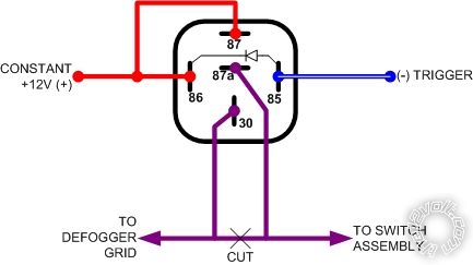
You can use this diagram for your particular application. Ensure that you program the blue/white wire for latched output. The diode is optional but it is recommended.
viper 5902 defroster connection -- posted image.
This information is provided only as a reference.
All circuits should be verified with a digital multi-meter prior to making any connections.
lurch228 
Silver - Posts: 1,338
Silver spacespace
Joined: August 08, 2012
Posted: November 13, 2012 at 1:50 AM / IP Logged  
You can also test to see if jumping (touch & release) one of the +12v wires to the +12v when button pressed, turns on the defrost (lights up the switch). If it does you don't need to cut the factory defrost wire just tap the relay into the +12v to 87,86 and the +12v when pressed to 30, 85 to trigger (set to pulse) This way the switch will time out just like normal, as if you pressed the button. This method is the preferred way so if the defrost mode is turned on in the summer the factory switch will shut it off by resistence instead of being latched until the remote start shuts off.
Sounds like a trip to an authorized dealer is in order to get the activation properly registered.
jcp0575 
Member - Posts: 8
Member spacespace
Joined: July 22, 2010
Location: Pennsylvania, United States
Posted: November 13, 2012 at 12:53 PM / IP Logged  
Thank you for the diagram. I'll try this weekend.
soundnsecurity 
Gold - Posts: 2,711
Gold spaceThis member has made a donation to the12volt.com. Click here for more info.spacespace
Joined: November 10, 2008
Location: Louisiana, United States
Posted: November 13, 2012 at 5:57 PM / IP Logged  
lurch228 wrote:
You can also test to see if jumping (touch & release) one of the +12v wires to the +12v when button pressed, turns on the defrost (lights up the switch). If it does you don't need to cut the factory defrost wire just tap the relay into the +12v to 87,86 and the +12v when pressed to 30, 85 to trigger (set to pulse) This way the switch will time out just like normal, as if you pressed the button. This method is the preferred way so if the defrost mode is turned on in the summer the factory switch will shut it off by resistence instead of being latched until the remote start shuts off.
Sounds like a trip to an authorized dealer is in order to get the activation properly registered.
its not a very smart thing to just jump the 12v wires together, what if the switched wire rests at ground? you will blow a fuse or fry the control. if you want to jump the wires then you need to test it first to make sure the wire doesnt rest at ground. at the very least you need a 1A fuse inline when you go jumping wires to see if they work.
howie ll 
Pot Metal - Posts: 16,466
Pot Metal spacespace
Joined: January 09, 2007
Location: United Kingdom
Posted: November 13, 2012 at 6:13 PM / IP Logged  
91stt's diagram is 100% correct, also X 2 with soundnsecurity, sorry Lurch you are quite WRONG in what you suggest, but then we had this out last week didn't we.
What part of motor wire/hot window feed is GROUNDED at rest don't you realise.
jcp0575 
Member - Posts: 8
Member spacespace
Joined: July 22, 2010
Location: Pennsylvania, United States
Posted: November 13, 2012 at 8:01 PM / IP Logged  
I can't wait till the weekend to hook this up. Is there anyway to correct the aux channels on the smartstart activation site. They are active on the Viper through my bit writer and active on my smartstart app on my phone, just not active through smartstart. Again, I appreciate all of your input.
lurch228 
Silver - Posts: 1,338
Silver spacespace
Joined: August 08, 2012
Posted: November 13, 2012 at 9:03 PM / IP Logged  
howie ll wrote:
91stt's diagram is 100% correct, also X 2 with soundnsecurity, sorry Lurch you are quite WRONG in what you suggest, but then we had this out last week didn't we.
What part of motor wire/hot window feed is GROUNDED at rest don't you realise.
I've been doing the older chevrolet cavaliers and the like from the late 80's early to mid 90's that way for years, and it works flawlessly. I have a 1989 Chevy Cavalier that is hooked up this way and has been since 1994 and is still working to this day.
Common sense to test the wires first, if the wire goes direct to the rear element it can be hooked up that way. If not on the GM's it will be a feed to a relay, and will need to be latched. I wouldn't tell him to try this if it would damage the vehicle and as far as I know it only applies to GM's and that is what he is working on.
But that's why we need to know how to test first don't we. If he doesn't know how to test then he shouldn't be attempting this install!
91stt 
Silver - Posts: 564
Silver spaceThis member consistently provides reliable informationspace
Joined: May 24, 2006
Location: New Jersey, United States
Posted: November 13, 2012 at 10:14 PM / IP Logged  
Your 1999 Tahoe has an integrated solid state timer delay relay in the HVAC control switch assembly that operates the defogger for 10 minutes. The recommendation is to make your connections as indicated in the diagram provided. This is the safest method to activate the defogger. Tapping the violet wire with 12 volts will backfeed the control switch and may damage it since it is not known what is in that little black box. This method will work regardless of whether the wire normally rest at ground or not and will isolate the upstream components. The time and cost to cut and make the extra connection is insignificant compared to the cost to replace the control unit if it is damaged from the 12V backfeed.
Although not shown in the diagram, the 12 volt supply must be fused. Use a 30A fuse to match the factory fuse size.
This information is provided only as a reference.
All circuits should be verified with a digital multi-meter prior to making any connections.
lurch228 
Silver - Posts: 1,338
Silver spacespace
Joined: August 08, 2012
Posted: November 13, 2012 at 10:35 PM / IP Logged  
On the older swtches it is a latched relay circuit with a resistance based shut off as the element heats up the resistance changes when it hits the set resistance it shuts off. The new ones may be solid state but if it direct feeds to the element, then it's using a latched based allbeit solid state relay to engage the output. The only change is the circuit is timer based instead of resistance. And the timer gets it voltage from the output side of the unit. So it is basicly backfeeding the timer by design, so triggering the relay and timer with a pulse would be no different than pushing the button.
This is only tested to work on GM direct feed to defogger element type systems.
Page of 2

  Printable version Printable version Post ReplyPost New Topic
You cannot post new topics in this forum
You cannot reply to topics in this forum
You cannot delete your posts in this forum
You cannot edit your posts in this forum
You cannot create polls in this forum
You cannot vote in polls in this forum

  •  
Search the12volt.com
Follow the12volt.com Follow the12volt.com on Facebook
Thursday, May 2, 2024 • Copyright © 1999-2024 the12volt.com, All Rights Reserved Privacy Policy & Use of Cookies
Disclaimer: *All information on this site ( the12volt.com ) is provided "as is" without any warranty of any kind, either expressed or implied, including but not limited to fitness for a particular use. Any user assumes the entire risk as to the accuracy and use of this information. Please verify all wire colors and diagrams before applying any information.

Secured by Sectigo
the12volt.com spacer
Support the12volt.com
Top
the12volt.com spacer