the12volt.com spacer
icon

r code for 2005 silverado remote start


Post ReplyPost New Topic
< Prev Topic Next Topic >
Mwsounds 
Copper - Posts: 61
Copper spacespace
Joined: January 04, 2005
Location: Alaska, United States
Posted: May 25, 2013 at 3:14 AM / IP Logged  
Hi,
I have installer a Viper 5704v in a 2005 Silverado club cab. I finally got the locks working and the door trigger is finicky, but the remote start will not work.
I Hooked up the Tach wire to one of the ignition coils... red wire.
I used the 555T and the 456G for the door locks and door trigger.
The 555T is hooked up as follows:
Red + connected to 12V constant
Black - connected to ground
Violet, Brown, and Orange are Ground Inputs and out puts connected to the blue - status wire from the remote starter with a diode between the to components.
White to the ground of the Passlock Cables
Blue to the key side of the resistance wire
blue/white to the Panel side of the resistance wire
It says to turn the key to the crank position while reading the Ohm load from the key side of the resistance wire long enough to get a reading but not long enough to start it... then back to the run position. This is supposed to activate the R code.
I have done that reading like 7 times and get different reading each time... having to wait ten minutes between tries...
from 4458 ohms to 6366 ohms... none of these setting are working for me.
Can anyone help me with this? I have spent 12 hours on this and needed to step away to clear my mind...
Thank you in advance!
God Bless!
Mike Ward
Thanks,
Mike Ward
Get it done right the first time!
tonanzith 
Gold - Posts: 593
Gold spaceThis member consistently provides reliable informationspace
Joined: July 18, 2008
Location: Washington, United States
Posted: May 25, 2013 at 6:08 PM / IP Logged  
Depending on the vehicle we will be looking for 3 wires bundled their colours are
(Group1)RED / White     Yellow     Black
(Group 2)RED / White     Yellow     ORANGE / Black
Remove the appropriate dash panels to get to the wire harness.
Locate the Pass Lock 2 Wires, they will be coming out of the ignition OR on the BCM they will be located in the grey connector, Pin A6 is your yellow wire, and pin B6 will be a black wire(they should be right beside each other).
Strip some of the wire insulation off the black wire, leaving it bare so you can test and solder to it later. DO NOT CUT THIS WIRE!
Now cut the yellow wire, make sure to leave enough on both ends to give yourself something to work with. Strip both of the cut ends for testing.
Take your digital ohm meter and put your negative probe on the black wire that you stripped back earlier. Put the positive probe on the yellow end of the wire that leads BACK to the ignition. Use alligator clips here to help the probes grab the wires.
With the probes hooked up turn the ignition to the run position. Don't try to actually start the vehicle, it won’t run anyways :). Read the ohm reading of the meter this is the resistance that we need to create to fool the PassLock security. Turn off the car.
When selecting a resistance don’t worry about being dead on sometimes being close is good enough. If you can’t find something anywhere near to what you read on the ohm meter you have the option to use a resistor between 0.5K ohms up to 13.6K ohms.
With the probes disconnected, take the resistor you selected and attach one of the ends to the black wire and then attach the other end to yellow wire that leads away from the ignition (goes to the computer). Apply black electrical tape to the yellow wire end that goes to the ignition, we don’t need it anymore.
With the resistor connected try and start your car, if you matched the resistance the car will start on the first or second try.
If it starts then SUCCESS! Solder all your new connections. Tape up your bare wires and re-assemble your dash you’re done :)
If it doesn’t start don’t freak out. You will have to do the factory relearn procedure(really easy)
I Always recommend using relays instead of a permenant bypass but the choice is yours.
Gary Sather
Mwsounds 
Copper - Posts: 61
Copper spacespace
Joined: January 04, 2005
Location: Alaska, United States
Posted: May 26, 2013 at 5:28 AM / IP Logged  
Thanks Gary! I will give that a shot and let you know how it turns out.
Thanks,
Mike Ward
Get it done right the first time!
Mwsounds 
Copper - Posts: 61
Copper spacespace
Joined: January 04, 2005
Location: Alaska, United States
Posted: May 26, 2013 at 5:31 PM / IP Logged  
Gary,
That seemed to do the trick, though the instructions said to actually crank the key momentarily to get the reading.
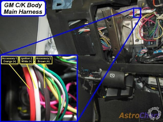
Also, I found that the second ignition was not white, in fact there was not a white wire in the whole bundle, it was actually orange and the accessory was actually the second yellow wire.
THe only think I see now is the parking brake and ABS light come on when remote started, but go away when the key is put in.
It there a fix for that?
Thank again!
Thanks,
Mike Ward
Get it done right the first time!
tonanzith 
Gold - Posts: 593
Gold spaceThis member consistently provides reliable informationspace
Joined: July 18, 2008
Location: Washington, United States
Posted: May 26, 2013 at 5:48 PM / IP Logged  
I don't believe that's an issue with the passlock bypass. That's usually caused by not having ALL tue accessories and or ignition wires powered up during remote start. Also can be caused by powering the accessories as ignition during remote start.   You should have two ignition wires. One pink and one white. You should also have two accessory wires. One orange and one brown. Believe me. They ARE there. Power The all properly and you will not have the service lights during remote start. r code for 2005 silverado remote start -- posted image.
Gary Sather

Sorry, you can NOT post a reply.
This topic is closed.

  Printable version Printable version Post ReplyPost New Topic
You cannot post new topics in this forum
You cannot reply to topics in this forum
You cannot delete your posts in this forum
You cannot edit your posts in this forum
You cannot create polls in this forum
You cannot vote in polls in this forum

  •  
Search the12volt.com
Follow the12volt.com Follow the12volt.com on Facebook
Friday, May 3, 2024 • Copyright © 1999-2024 the12volt.com, All Rights Reserved Privacy Policy & Use of Cookies
Disclaimer: *All information on this site ( the12volt.com ) is provided "as is" without any warranty of any kind, either expressed or implied, including but not limited to fitness for a particular use. Any user assumes the entire risk as to the accuracy and use of this information. Please verify all wire colors and diagrams before applying any information.

Secured by Sectigo
the12volt.com spacer
Support the12volt.com
Top
the12volt.com spacer