the12volt.com spacer
icon

01 suburban, remote start problems


Post ReplyPost New Topic
< Prev Topic Next Topic >
rezintexas 
Member - Posts: 6
Member spacespace
Joined: May 27, 2013
Location: Texas, United States
Posted: May 27, 2013 at 3:39 PM / IP Logged  
Hello all, first post. Looking for some help. Any insight is appreciated!
Vehicle: 2001 Chevy Suburban 2500 4x4. It came factory with the 6.0, but now has a 6.3 built stroker motor and custom street tune by Patrick Guerra.
Alarm / Remote Start system is a Clifford Matrix 510.4X. I'm also using an IB-BMBP bypass module.
I have installed maybe 10 car stereos, one previous remote start system in a '96 Acura, and I built and swapped my LS-based stroker engine myself - so I know my way around a car. This system, however is kicking my butt these last few days.
First of all, I used this link as the baseline for my install:
https://www.the12volt.com/installbay/forum_posts.asp~TID~50790
Tons of helpful info in there, however some of the wire colors listed are wrong for my vehicle. I'm not sure if it's because my truck is a 2500 or not:
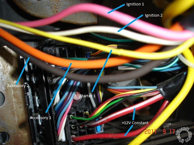
1. The 12-awg orange wire in my ignition switch harness is an ignition wire. The link above says it's an accessory wire.
2. The 16-awg white wire in my ignition switch harness is a accessory wire (key forward one click). The link above says it's an ignition wire.
3. The 12-awg brown wire in my ignition switch harness is a 2nd accessory wire (key back one click). The link above does not specify a 2nd accessory wire.
As the truck sits today, the system is installed and all relevant connections are made (as far as I know). I installed the IB-BMBP module per instructions and I got the 4 blinks from the LED to indicate successful programming. I have also gone into the alarm menu to change transmission type to Automatic, changed the "Engine Checking Mode" to Tachometer, and changed the cranking time to 1.2 seconds.
Here is what WORKS:
1. Keyless entry. I used relays to transfer the negative output signal to a positive signal, and the locks work as they should.
2. Door triggers. I used the (-) input wire and diodes to isolate the individual circuits. The alarm will go off if a door is opened while armed.
3. Hood trigger, works as the doors do.
4. Siren. It chirps on lock/unlock, and will go full on when a door triggers the alarm.
Here is what DOESN'T WORK:
1. Remote start. When I push the button, nothing happens. About 10 seconds later, I hear the "brain" of the system make switching noises, like a relay turning on and off (click-a sound). It does this 7 times. I read somewhere else that I may need a "self learning" bypass module because I have a custom tune on my vehicle - I don't know anything else about that.
2. Shock sensor - Stinger Doubleguard. No matter what the sensitivity is set at, it will not trigger the alarm at all. It is currently connected to the brain with just the blue signal wire and power/ground. The green wire is jumpered to the blue wire at the sensor output. The LED inside the shock sensor will not light up at all.
3. Parking lights - I cannot measure any signal coming from the "PARKING LIGHT OUTPUT" from the brain, when I push the lock/unlock buttons. There is no signal at all, positive or negative. I have, however, located the correct wire to tie into. This wire takes a straight +12V signal to illuminate the parking lights.
Here is how I made my connections:
1.     Chassis ground to body of truck. I measured 0.1-0.2 Ohm resistance to the battery terminal from this ground point.
2.     12V power with 8-awg wire and 30a fuse through grommet in firewall.
3.     Starter input and output are as they should be.
4.     Neutral safety switch is plugged in and ON.
5.     The "(-) NEUTRAL SAFETY INPUT" wire is connected to ground.
6.     The Brown "(-) INPUT" wire from the IB-GMBP module is connected to the "(-) 200mA STATUS OUTPUT" on the brain.
7.     The "TACHOMETER INPUT" wire is connected to the white wire at pin #10 of the red PCM connector.
8.     The "(+) BRAKE SHUTDOWN INPUT" wire is connected to the white wire at the pedal switch assembly.
9.     The "(-) 200mA OEM ALARM DISARM OUTPUT" wire is connected to the correct wire in the truck BCM harness.
The following wires are currently not connected to anything:
PARKING LIGHT ISOLATION WIRE - PIN 87a of onboard relay
(-) 500mA GROUND WHEN ARMED OUTPUT
(+) FLEX RELAY INPUT 87A key side (if required) of FLEX RELAY
(-) 200mA IGNITION / FLEX RELAY CONTROL OUTPUT
(-) 200mA 2ND STATUS / REAR DEFOGGER OUTPUT
(-) 200mA TRUNK RELEASE OUTPUT
(-) 200mA DOME LIGHT SUPERVISION OUTPUT
(-) 200mA HORN HONK OUTPUT
(-) 200mA IGNITION 1 OUTPUT
(-) 200mA AUX 3 OUTPUT
(+) DOOR TRIGGER INPUT
(-) 200mA AUX 1 OUTPUT
(-) 200mA AUX 2 OUTPUT
(-) 200mA AUX 4 OUTPUT
(-) 200mA STARTER OUTPUT
(-) TRUNK PIN / INSTANT TRIGGER INPUT (N/C OR N/O)
(-) DIESEL WAIT TO START INPUT
(-) REMOTE START TURBO TIMER ACTIVATION INPUT
(-) 200mA ACCESSORY OUTPUT
(-) 200mA OEM ALARM ARM OUTPUT
Sorry for the long post, I am very detail-oriented and I didn't want to leave anything out.
I am grateful for any help or direction with these problems.
Thanks for reading.
Matt
2001 Suburban 2500 4x4
2006 Magnum SRT8
kreg357 
Platinum - Posts: 7,783
Platinum spaceThis member has made a donation to the12volt.com. Click here for more info.spaceThis member has been recognized as an authority in Electrical Theory. Click here for more info.spaceThis member has been recognized as an authority in Mobile Security and Convenience. Click here for more info.spacespace
Joined: January 30, 2009
Location: Pennsylvania, United States
Posted: May 27, 2013 at 4:59 PM / IP Logged  
Hi Matt,
Looks like you did good so far. I might be able to help with the R/S portion. I believe the Clifford unit is the same as a Viper.
Verify that the H3 harness is all connected like shown below :
1 PINK (+) IGNITION 1 INPUT/OUTPUT       Pink
2 RED / WHITE (30A) FUSED Flex Relay       Red
3 ORANGE ACCESSORY OUTPUT              Orange
4 VIOLET (+) STARTER OUTPUT (CAR SIDE)        Yellow
5 GREEN (+) STARTER INPUT (KEY SIDE)            Yellow
6 RED (+) FUSED (30A) IGNITION 1 INPUT  Red
7 PINK/WHITE (+) IGNITION 2 / FLEX RELAY OUTPUT     White **Set as IGN2
8 PINK/BLACK FLEX RELAY INPUT 87A FLEX RELAY       Not Used
9 RED / BLACK FUSED (30A) ACC/STARTER INPUT          Red
10 N/C N/C   
There might be two Red +12V power wires or one Red and one RED / White +12V power wires in the ignition harness.
Here is a photo of a 2002 Silverado ignition harness by the BCM. The Brown ACC2 wire might optional and would require an additional
30/40 SPDT relay and a 30 Amp fuse.
01 suburban, remote start problems -- posted image.
The seven blinks when you attempt a remote start usually indicates that you are still in Manual Trans Mode. It can be difficult to change
options with the remotes. A BitWriter makes life easier.
On the Parking Light problem, check the Clifford brain for the internal Parking Light Jumper/Fuse. Typically it becomes dislodged during
shipment. Make sure it is plugged in / set to (+).
Soldering is fun!
rezintexas 
Member - Posts: 6
Member spacespace
Joined: May 27, 2013
Location: Texas, United States
Posted: May 29, 2013 at 6:25 PM / IP Logged  
Kreg,
Great advice, thanks for your time.
I got the RS working by doing the programming step again (with remote). Don't know why it didn't work the first time!
I also got the parking lights working by installing the internal fuse on the alarm brain. The lame instructions did not include that step...
The shock sensor still does not work. Any ideas there?
The picture you posted does not match the wires in my truck. The orange is an ignition wire (hot with key in ON position - 2 clicks forward), the white wire is an accessory wire (hot with key one click forward), and the brown wire is the primary accessory wire (hot with key one click backwards - runs the radio, mirrors, windows, wipers).
Thanks again for the help.
Matt
2001 Suburban 2500 4x4
2006 Magnum SRT8
kreg357 
Platinum - Posts: 7,783
Platinum spaceThis member has made a donation to the12volt.com. Click here for more info.spaceThis member has been recognized as an authority in Electrical Theory. Click here for more info.spaceThis member has been recognized as an authority in Mobile Security and Convenience. Click here for more info.spacespace
Joined: January 30, 2009
Location: Pennsylvania, United States
Posted: May 29, 2013 at 9:29 PM / IP Logged  

Glad to hear it is working now.  The Viper error diagnostics can be a big help at times.

I believe the main factor in determining whether a wire is an Accessory or Ignition wire

has to do with how it behaves when the key is in the Start position.  An Ignition wire will
maintain +12V in the Start position and an Accessory wire will drop the +12V in the Start
position.    Accessory wires will be +12V in the ON or Run position but if it is a high draw
item ( like fans or compressor ) it will drop during cranking and also be off in the ACC
position.  Most vehicles that have an ACC key position don't run the fans, etc.

Either way, I would recommend connecting the White wire as an Ignition wire

to prevent any transmission problems.

I am not a big Directed user and can't help too much with the Stinger Doubleguard shock

sensor, sorry 

Soldering is fun!
rezintexas 
Member - Posts: 6
Member spacespace
Joined: May 27, 2013
Location: Texas, United States
Posted: June 15, 2013 at 6:51 AM / IP Logged  
kreg, I have not moved the wite wire to ignition yet, although it still gets power when in "run" position. No tranny shifting issues at the moment.
However my cruise control is now not working. There is no light on the dash, and the fuse is fine.
Any ideas?
2001 Suburban 2500 4x4
2006 Magnum SRT8
kreg357 
Platinum - Posts: 7,783
Platinum spaceThis member has made a donation to the12volt.com. Click here for more info.spaceThis member has been recognized as an authority in Electrical Theory. Click here for more info.spaceThis member has been recognized as an authority in Mobile Security and Convenience. Click here for more info.spacespace
Joined: January 30, 2009
Location: Pennsylvania, United States
Posted: June 15, 2013 at 8:09 AM / IP Logged  
While I don't think the cruise control problem is related to the Clifford system, I believe your first
priority would be to connect the H3 wires to the truck properly. All of the GM's similar to your truck
that I have done have the following set-up :
Red and RED / White are +12V constant
Pink and White are the Ignition wires.
Orange and Brown are the Accessory wires.
Yellow is the Starter wire.
Of course, testing with a DMM is required to verify this.
While the Brown Accessory wire might not be required ( it usually controls the power windows and
other non-essential items ), powering it with an extra, external, relay will ensure the R/S is duplicating
everything a normal key start would do.
My guess on the cruise control is that a wire or connector has become un-seated, if it doesn't turn
out to be a totally separate / coincidental / unrelated problem.
Soldering is fun!
rezintexas 
Member - Posts: 6
Member spacespace
Joined: May 27, 2013
Location: Texas, United States
Posted: June 15, 2013 at 4:07 PM / IP Logged  
Kreg,
with my truck, here is what I verified with a DMM:
Orange wire: hot with 2 key clicks forward (run position)
White wire: hot with 1 key click forward and 2 key clicks forward
Brown wire: hot with 1 key click backwards
Is that consistent with your understanding of "ignition" and "accessory wires"?
thanks.
2001 Suburban 2500 4x4
2006 Magnum SRT8
kreg357 
Platinum - Posts: 7,783
Platinum spaceThis member has made a donation to the12volt.com. Click here for more info.spaceThis member has been recognized as an authority in Electrical Theory. Click here for more info.spaceThis member has been recognized as an authority in Mobile Security and Convenience. Click here for more info.spacespace
Joined: January 30, 2009
Location: Pennsylvania, United States
Posted: June 15, 2013 at 4:29 PM / IP Logged  
The main distinguishing characteristic between an Accessory wire and an Ignition wire for me is how it behaves in the Start position.   A true Ignition wire
will remain at +12V during Starter cranking, an Accessory will drop it's +12 volts during cranking. While this is a basic general rule, there can be exceptions.
Soldering is fun!

Sorry, you can NOT post a reply.
This topic is closed.

  Printable version Printable version Post ReplyPost New Topic
You cannot post new topics in this forum
You cannot reply to topics in this forum
You cannot delete your posts in this forum
You cannot edit your posts in this forum
You cannot create polls in this forum
You cannot vote in polls in this forum

  •  
Search the12volt.com
Follow the12volt.com Follow the12volt.com on Facebook
Sunday, April 28, 2024 • Copyright © 1999-2024 the12volt.com, All Rights Reserved Privacy Policy & Use of Cookies
Disclaimer: *All information on this site ( the12volt.com ) is provided "as is" without any warranty of any kind, either expressed or implied, including but not limited to fitness for a particular use. Any user assumes the entire risk as to the accuracy and use of this information. Please verify all wire colors and diagrams before applying any information.

Secured by Sectigo
the12volt.com spacer
Support the12volt.com
Top
the12volt.com spacer