the12volt.com spacer
icon

2001 echo remote start ign2 confusion


Post ReplyPost New Topic
< Prev Topic Next Topic >
echooooo 
Member - Posts: 3
Member spacespace
Joined: December 13, 2013
Location: Massachusetts, United States
Posted: December 13, 2013 at 8:37 PM / IP Logged  
OK I have an auto command 40026 and cant get it to work on my 2001 Toyota Echo. I'm stumped on where to connect the required 5-pin relay to the unit. Since that is the trigger for the relay, but the other side already has 12v per diagram, I need a pin on the unit that will go to ground.
When the relay trips, it interrupts the IGN2 wire, by the way. Just dont have a pin on the unit that grounds when activated.
Also, I cant seem to get the unit to operate unless the key is already on and car running, in which case I can click the remote which clkicks the auto command relays and I can then remove the key and car stays running, A press of the remote (or brake pedal) shuts the car off.
So the unit is ALMOST working. But I'm stumped... any advice appreciate. Advice which solves my problem REALLY appreciated! ;)
MANUAL
http://www.readyremote.com/pdf/manuals/40026.pdf
RELAY ADDENDUM
http://www.readyremote.com/main.asp?action=select&yr=3113&product=Remote%20Start&make=Toyota&model=Echo#
kreg357 
Platinum - Posts: 7,783
Platinum spaceThis member has made a donation to the12volt.com. Click here for more info.spaceThis member has been recognized as an authority in Electrical Theory. Click here for more info.spaceThis member has been recognized as an authority in Mobile Security and Convenience. Click here for more info.spacespace
Joined: January 30, 2009
Location: Pennsylvania, United States
Posted: December 13, 2013 at 9:03 PM / IP Logged  

Follow the diagram on Page 2 in the TechTip #1077 :

https://www.the12volt.com/installbay/file.asp?ID=1060

Use the WHITE/ Black (-) 400mA  Ignition3 output wire.

Soldering is fun!
echooooo 
Member - Posts: 3
Member spacespace
Joined: December 13, 2013
Location: Massachusetts, United States
Posted: December 13, 2013 at 11:32 PM / IP Logged  
kreg357 wrote:

Follow the diagram on Page 2 in the TechTip #1077 :

https://www.the12volt.com/installbay/file.asp?ID=1060

Use the WHITE/ Black (-) 400mA  Ignition3 output wire.

Thanks, but that diagram says to connect to IGN or ACC, both 12v + sources on the remote starter unit. The other side of the relay trigger is already 12v + so the relay wouldn't ever trigger based on that configuration. I have a diff unit coming to try anyways...
kreg357 
Platinum - Posts: 7,783
Platinum spaceThis member has made a donation to the12volt.com. Click here for more info.spaceThis member has been recognized as an authority in Electrical Theory. Click here for more info.spaceThis member has been recognized as an authority in Mobile Security and Convenience. Click here for more info.spacespace
Joined: January 30, 2009
Location: Pennsylvania, United States
Posted: December 14, 2013 at 4:11 AM / IP Logged  

OK but...

That TechTip #1077 diagram is "generic".  Depending on the vehicle needs, you might have to use a relay to isolate an
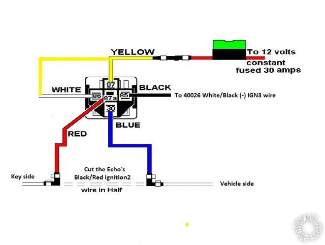
Ignition wire or an Accessory wire.  With the Echo, it's the IGN2 wire.  Here is the exact relay wiring for your exact car,
using the 40026 remote starter system :
Relay Pin 85 to 40026 WHITE/ Black (-) IGN3 wire
Relay Pin 86 and 87 to +12V constant thru fuse
Relay Pin 87A to ignition switch side of cut Echo BLACK/ Red IGN2 wire
Relay Pin 30 to vehicle side of cut Echo BLACK/ Red IGN2 wire

The 40026's thick Green IGN2 wire would not used.

Soldering is fun!
kreg357 
Platinum - Posts: 7,783
Platinum spaceThis member has made a donation to the12volt.com. Click here for more info.spaceThis member has been recognized as an authority in Electrical Theory. Click here for more info.spaceThis member has been recognized as an authority in Mobile Security and Convenience. Click here for more info.spacespace
Joined: January 30, 2009
Location: Pennsylvania, United States
Posted: December 14, 2013 at 4:27 AM / IP Logged  

Here is a diagram ( the relays actual harness wire colors might be different on your relay )

2001 echo remote start ign2 confusion -- posted image.

Soldering is fun!
echooooo 
Member - Posts: 3
Member spacespace
Joined: December 13, 2013
Location: Massachusetts, United States
Posted: December 14, 2013 at 10:27 AM / IP Logged  
THANKS! for the info. Unfortunately :( my unit does not have an IGN3 on it. So looks like it wont work. I ordered an Avital 4113L but looking at the diagram, not sure if it will work either. Because I'm not sure what that IGN2 actually does when the unit tries to start the car. I suppose I need now to look at the Echo wiring diagram and learn what IGN2 is all about.
AVITAL INSTALLATION:
http://www.directeddealers.com/manuals/IG/Avital/N4113_2008-07print.pdf

Sorry, you can NOT post a reply.
This topic is closed.

  Printable version Printable version Post ReplyPost New Topic
You cannot post new topics in this forum
You cannot reply to topics in this forum
You cannot delete your posts in this forum
You cannot edit your posts in this forum
You cannot create polls in this forum
You cannot vote in polls in this forum

  •  
Search the12volt.com
Follow the12volt.com Follow the12volt.com on Facebook
Tuesday, April 30, 2024 • Copyright © 1999-2024 the12volt.com, All Rights Reserved Privacy Policy & Use of Cookies
Disclaimer: *All information on this site ( the12volt.com ) is provided "as is" without any warranty of any kind, either expressed or implied, including but not limited to fitness for a particular use. Any user assumes the entire risk as to the accuracy and use of this information. Please verify all wire colors and diagrams before applying any information.

Secured by Sectigo
the12volt.com spacer
Support the12volt.com
Top
the12volt.com spacer