the12volt.com spacer
icon

2002 dodge dakota remote start install


Post ReplyPost New Topic
< Prev Topic Next Topic >
outshined93 
Member - Posts: 4
Member spacespace
Joined: January 19, 2014
Location: Pennsylvania, United States
Posted: January 19, 2014 at 3:31 PM / IP Logged  
Hello all,
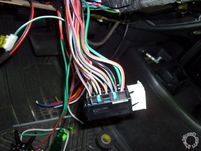
Just bought and installed a CrimeStopper RS4-G4 in a 2002 dodge dakota 4.7 quad cab. I've found all the wires and have it starting with the remote start but my question is: There are three ignition wires but so far i've only hooked the start up to one wire, a dark blue one according to diagrams and it starts fine. Should i splice the 2 ignition wires together so they start off of one? I also get a check engine light and from what i've found, it is because the 3rd wire isn't hooked up, which powers the TCM and trips when it doesn't get power with the remote start.
With this crimestopper unit, it has a seperate optional wire for ignition and is pre-programmed that way. Could I hook that up to the 3rd ignition wire to keep the CEL off or should I run a relay? I've read bits and pieces in some places about running a relay to power the extra ignition wires.
Sorry for the long post, just wanted to try and be as specific as possible. Thanks in advance for any help!
Thanks,
James
kreg357 
Platinum - Posts: 7,783
Platinum spaceThis member has made a donation to the12volt.com. Click here for more info.spaceThis member has been recognized as an authority in Electrical Theory. Click here for more info.spaceThis member has been recognized as an authority in Mobile Security and Convenience. Click here for more info.spacespace
Joined: January 30, 2009
Location: Pennsylvania, United States
Posted: January 19, 2014 at 4:17 PM / IP Logged  

Lots of Ignition type wires on that truck.  I would power them all and keep them on separate circuits.  Use relays if necessary.

2002 dodge dakota remote start install -- posted image.

Soldering is fun!
outshined93 
Member - Posts: 4
Member spacespace
Joined: January 19, 2014
Location: Pennsylvania, United States
Posted: January 19, 2014 at 4:24 PM / IP Logged  
Ok that makes sense. Would you happen to have a diagram or link that would show me which pins to use on the relays to provide power?
Thanks for the quick reply!
kreg357 
Platinum - Posts: 7,783
Platinum spaceThis member has made a donation to the12volt.com. Click here for more info.spaceThis member has been recognized as an authority in Electrical Theory. Click here for more info.spaceThis member has been recognized as an authority in Mobile Security and Convenience. Click here for more info.spacespace
Joined: January 30, 2009
Location: Pennsylvania, United States
Posted: January 19, 2014 at 5:21 PM / IP Logged  

Assuming that you are using the Yellow/Black (-) Ignition1 output for a bypass module.

I am not a CrimeStopper user and the RS4 manual I have might be out of date.  There might be better ways to do this but...

Think I would use two 30/40 Amp SPDT relays, controlled by the RS4  Pink/White wire set to to IGN2.  Here is the wiring :

Relay 1 ( for Ign2 )

Pin 85 to Chassis Ground
Pin 86 to RS4 Pink/White
Pin 87 to +12V constant thru 20 Amp fuse
Pin 30 to Dakota Ign2
Pin 87a not used

Relay 2 ( for Ign3 )

Pin 85 to Chassis Ground
Pin 86 to RS4 Pink/White
Pin 87 to +12V constant thru 20 Amp fuse
Pin 30 to Dakota Ign3
Pin 87a not used

Soldering is fun!
outshined93 
Member - Posts: 4
Member spacespace
Joined: January 19, 2014
Location: Pennsylvania, United States
Posted: January 19, 2014 at 6:28 PM / IP Logged  
I don't have security for the truck but I am using the yellow starter wire. Thanks for the diagram and the help!
kreg357 
Platinum - Posts: 7,783
Platinum spaceThis member has made a donation to the12volt.com. Click here for more info.spaceThis member has been recognized as an authority in Electrical Theory. Click here for more info.spaceThis member has been recognized as an authority in Mobile Security and Convenience. Click here for more info.spacespace
Joined: January 30, 2009
Location: Pennsylvania, United States
Posted: January 19, 2014 at 7:59 PM / IP Logged  

Not sure what Yellow Starter wire is.  The RS4 Install guide I have doesn't show one.

If you are not using the RS4 Yellow/Black (-) Run ( Ign1 ) wire for anything, you could save yourself a relay and do it this way :

RS4 thick Pink Ign1 to Dakota IGN1

RS4 thick Pink/White ( set to Ign2 ) to Dakota Ign2

Relay for Dakota Ign3

Relay Pin 85 to RS4 Yellow/Black (-) Run ( Ign1 )
Relay Pins 86 and 87 to +12V constant thru 20 Amp fuse
Relay Pin 30 to Dakota Ign3
Relay Pin 87a not used

Soldering is fun!
outshined93 
Member - Posts: 4
Member spacespace
Joined: January 19, 2014
Location: Pennsylvania, United States
Posted: January 19, 2014 at 8:18 PM / IP Logged  
sorry I should've meant the yellow start wire on the trucks ignition. using one relay will make it a ton easier! thanks again!

Sorry, you can NOT post a reply.
This topic is closed.

  Printable version Printable version Post ReplyPost New Topic
You cannot post new topics in this forum
You cannot reply to topics in this forum
You cannot delete your posts in this forum
You cannot edit your posts in this forum
You cannot create polls in this forum
You cannot vote in polls in this forum

  •  
Search the12volt.com
Follow the12volt.com Follow the12volt.com on Facebook
Thursday, May 2, 2024 • Copyright © 1999-2024 the12volt.com, All Rights Reserved Privacy Policy & Use of Cookies
Disclaimer: *All information on this site ( the12volt.com ) is provided "as is" without any warranty of any kind, either expressed or implied, including but not limited to fitness for a particular use. Any user assumes the entire risk as to the accuracy and use of this information. Please verify all wire colors and diagrams before applying any information.

Secured by Sectigo
the12volt.com spacer
Support the12volt.com
Top
the12volt.com spacer