the12volt.com spacer
icon

window rollup module basics


Post ReplyPost New Topic
< Prev Topic Next Topic >
808pants 
Member - Posts: 6
Member spacespace
Joined: March 23, 2014
Location: Hawaii, United States
Posted: March 23, 2014 at 5:21 PM / IP Logged  
Maybe it's because I only work on older cars (that don't have factory window relays?), and definitely it's to do with the crappy schematics that come with every window rollup module I have been able to research...but I don't get how *any* of these could actually do what they're supposed to do - that is, without additional external relays and a lot of futzing that I'd rather not have to do to mount & wire them. To me, the point of getting one of these modules, as a companion to a remote-locking receiver, is precisely because I want it to be able to - independently - roll up the windows, after some simple cut/splice connections between my window-switches and motors. Window motors that I know are simple DC items that need both a ground and hot lead to move, and mine (at least) have no relay isolation (I assume some do, but my question still stands) - they're directly controlled by up/down switches. When a window-switch is in relaxed "normal" position, there's no ground or hot connection to the motor. So when a window module puts out a 12V signal, and it's even shown wired interrupting the switch lead to the motor, well...it leaves me baffled as to how that motor is going to move, since yeah, it's getting that 12V source, but it's not getting a ground.
Am I missing something, or can any of these work without external relays to interface them?
Dave
the12volt 
Administrator - Posts: 3,955
Administrator spaceThis member has made a donation to the12volt.com. Click here for more info.spaceThis member has been recognized as an authority in Electrical Theory. Click here for more info.spaceThis member has been recognized as an authority in Mobile Audio and Video. Click here for more info.spaceThis member has been recognized as an authority in Mobile Security and Convenience. Click here for more info.spacespace
Joined: March 07, 2002
Location: Louisiana, United States
Posted: March 23, 2014 at 5:40 PM / IP Logged  
Typically, but not all, window motors rest at ground through the switch. If yours do not, then you will need additional relays. The instructions (destructions) included should show this. If not, let us know.
window rollup module basics -- posted image. the12volt • Support the12volt.com
808pants 
Member - Posts: 6
Member spacespace
Joined: March 23, 2014
Location: Hawaii, United States
Posted: March 23, 2014 at 10:27 PM / IP Logged  
window rollup module basics -- posted image.
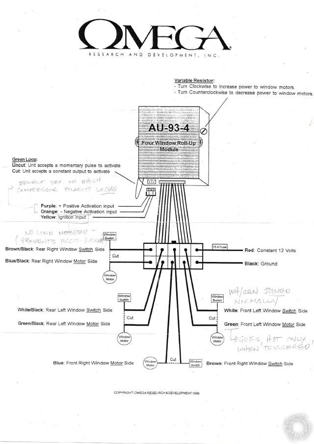
Scanned image of connection diagram is uploaded - my penciled notes are from bench-testing to verify how connection options worked. So I have to add relays to ground my motors, then? That's...annoying. I bought this model from a domestic seller & paid more via Amazon specifically because I thought they'd be responsive to my questions along these lines, if/when the instructions were no good - nope. Now I think I'd have been better off ordering directly from the PRC.
Couple weeks back, I did verify no ground exists at motors normally. Rocker switches just swap polarity to motors, as I'd assumed all would do, with center position being off & ungrounded.
Dave
itsyuk 
Silver - Posts: 505
Silver spacespace
Joined: February 23, 2010
Location: United States
Posted: March 24, 2014 at 1:22 AM / IP Logged  
what is the vehicle you are trying to use this on?
yuk
quiet rural missouri, near KC.
If your system moves you physically and not emotionally, you have wasted your money.
howie (aka: harryharris)
Silver - Posts: 355
Silver spacespace
Joined: February 17, 2014
Location: Florida, United States
Posted: March 24, 2014 at 1:55 AM / IP Logged  
If your motors are open circuit at rest, you have a system used by say 1% of vehicles.
Forgetting low current switching and BCM control on the newest vehicles, about 95% use NEG at rest, 4%, older Mercedes, VW use POS at rest so please stop moaning maybe you're just unlucky window rollup module basics -- posted image.
As itsyuk says make model and year?
Test before boxing up.
oldspark 
Gold - Posts: 4,913
Gold spacespace
Joined: November 03, 2008
Location: Australia
Posted: March 24, 2014 at 3:53 AM / IP Logged  
Hmmm - even I'm confused, at least without knowing the target wiring.
I wired my windows (retrofitted to a 1965 vehicle) using relays - ie, 2 SPDT per motor.
I wired rest at GND for both sides. (That is the obvious choice for safety reasons.)
In that AU-93-4 wiring diagram, I don't understand how it can say merely xxx Switch side or - more so - xxx Motor side without specifying the "up" direction - that's unless it's a dual motor system or the control uses f.ex 0V for off, 12V for up, 6V for down (but who'd so that?), OR if its a comms signal (CAN etc).
In my case the above unit would have to be after my relays - not between the switch & relays - to use its current sensing shut-off.
But in relation to the OP's problem, tho motors can be totally floating (open circuit) when off, that is the choice of the manufacturer etc. Usually it's easier leaving the connected when off (as in the case using 2 SPDT relays), but in others they'd be open (eg, if using 4 SPST relays instead of 2 SPDT).
For switches, longer and overlapping contacts/tracks are usually more reliable - ie, less contact to no-contact transitions - hence the GND at rest etc.
808pants 
Member - Posts: 6
Member spacespace
Joined: March 23, 2014
Location: Hawaii, United States
Posted: July 05, 2014 at 2:09 PM / IP Logged  
Finally getting back into this, months later. (Is there a rollup module that would work as-is, ex-factory, without all this futzing around with external relays?)
So:
1) I didn't have this thread set to notify me...oops...
2) Vehicle is a 1983 Mercedes-Benz 300SD
3) yeah, I hadn't squinted hard enough at my vehicle schematic to discover that the window switches rest the motor leads at +12V (something I think Howie was covering above), and those leads are SPLICED and dead when the ignition key is out...
4) ...so I guess I wasted a lot of time and created needless drama in my life by wiring up a 4PST relay, expecting it to ground what I'd /thought/ was simply the neg side of each motor, but which turns out to be a spliced set of leads to both sides of each motor - so when activated, the module was trying to send +12V to that same (now grounded and spliced) pair of leads.
Yeah, so no wonder a fuse blew, once I plugged the switches back in to test.
I now think that basically, my approach was polarity-reversed, with a twist, where the 4PST relay can't be used.
I did learn that the module closes each window in a sequence, presumably to minimize current through it.
So am I thinking right this time? I think my "simplest" fix would have to be to:
1) Use four /individual/ SPST relays, each inserted into respective motor /ground/ leads, as follows:
a) the common connected to motor (-),
b) the NC side to window control switch, and
c) each NO contact goes to ground (as does one side of the coil, while I am at it)
Thus, activate a relay, and it will open that pair of spliced motor leads, and give that motor a (-).
2) Splice the module's "motor" leads (4ea) to
a) each window motor's (+) side
b) each corresponding relay coil.
3) snip off and insulate the module's four "window switch" leads, since they can't be used for anything.
Am I overlooking anything (again)? It occurred to me that with the terrible documentation and quaint English supplied with this module, it's even possible that it might be internally-switchable so as to provide (-) to each window instead of (+), which would allow me to eliminate ALL relays.
--Pants
Dave
808pants 
Member - Posts: 6
Member spacespace
Joined: March 23, 2014
Location: Hawaii, United States
Posted: July 05, 2014 at 2:52 PM / IP Logged  
Shortly after posting, I found that a distributor of these modules came up with a much more efficient mod to fix this - and it uses just one SPST relay. It turns my brute-force fix inside out, by snipping the normal 12V supply to switches, so that they only operate "normally" when accessory-power closes their contacts - and otherwise they rest at ground, thus allowing the module to operate in "generic" mode.
Why didn't I think of that? (and...why didn't the OEM documentation come with something like this?)
window rollup module basics -- posted image.
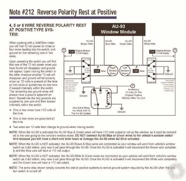
Other conditions are also shown in the augmented data-sheet at http://www.connect2car.com/Manuals/Au_93_4_window_module.pdf
Dave
howie ll 
Pot Metal - Posts: 16,466
Pot Metal spacespace
Joined: January 09, 2007
Location: United Kingdom
Posted: July 05, 2014 at 5:05 PM / IP Logged  
Well I did say 4% and your luck 80s Mercedes were that type, I believe the DEI 530t can do it without an external relay.
Plan B turn the feeds and grounds around the other way at the switches.
There was also an Italian Alarm company called Scorpion, they supplied Mercedes with dealer fit alarms (in England) and of course they had a custom window closer. But that was 30 years ago.
It's arcane knowledge these days, nearly all Euro and Japanese have one shot closing and all the motor wires are NEG at rest.
howie ll 
Pot Metal - Posts: 16,466
Pot Metal spacespace
Joined: January 09, 2007
Location: United Kingdom
Posted: July 06, 2014 at 6:48 AM / IP Logged  
It just occurred to me that if the power supply sits at ground with the ignition off and you only use the window closer with ignition off, you won't need a relay since all the wires will be at ground.
Page of 2

  Printable version Printable version Post ReplyPost New Topic
You cannot post new topics in this forum
You cannot reply to topics in this forum
You cannot delete your posts in this forum
You cannot edit your posts in this forum
You cannot create polls in this forum
You cannot vote in polls in this forum

  •  
Search the12volt.com
Follow the12volt.com Follow the12volt.com on Facebook
Thursday, April 18, 2024 • Copyright © 1999-2024 the12volt.com, All Rights Reserved Privacy Policy & Use of Cookies
Disclaimer: *All information on this site ( the12volt.com ) is provided "as is" without any warranty of any kind, either expressed or implied, including but not limited to fitness for a particular use. Any user assumes the entire risk as to the accuracy and use of this information. Please verify all wire colors and diagrams before applying any information.

Secured by Sectigo
the12volt.com spacer
Support the12volt.com
Top
the12volt.com spacer