the12volt.com spacer
icon

2007 Peugeot 308 Lock Trigger


Post ReplyPost New Topic
< Prev Topic Next Topic >
tafarelli 
Copper - Posts: 55
Copper spacespace
Joined: January 06, 2016
Location: Croatia
Posted: January 06, 2016 at 4:31 PM / IP Logged  
Hi I have been struggling to install cardot pke system in my Peugeot 308 1.6 hdi year 2007 for few days now. I have managed to install push start button and also pke function by connecting both lock and unlock wires to lock/unlock button wire on main console. The problem is they are both connected to same wire so when I push lock when locked it unlocks it. System has built in option that sends lock signal after minut or so no matter if the veichle is locked or not so when I leave it locks and after some time sends another lock signal which unlocks it so when I return it is unlocked:(
I have inspected wires in main doir and found three which correspond when locking/unlocking. One is 0 when unlocked and -12V when locked (unlock wire I think), the other us 0 when locked and -12V when locked(lock wire). Unlock wire triggers simply by grounding it but I am unable to trigger lock wire no matter hiw I connect it. Maybe it uses double pulse? Please help me any advice is much appreciated. Many thanks
dk
howie ll 
Pot Metal - Posts: 16,466
Pot Metal spacespace
Joined: January 09, 2007
Location: United Kingdom
Posted: January 07, 2016 at 2:50 AM / IP Logged  
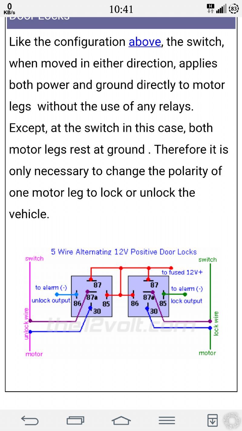
5 wire lock system on the vehicle body control.
You're looking for the motor wires.
tafarelli 
Copper - Posts: 55
Copper spacespace
Joined: January 06, 2016
Location: Croatia
Posted: January 07, 2016 at 3:47 AM / IP Logged  
Thanks for reply. Do you mean I have to connect relays as in attachment. 2007 Peugeot 308 Lock Trigger -- posted image.
dk
tafarelli 
Copper - Posts: 55
Copper spacespace
Joined: January 06, 2016
Location: Croatia
Posted: January 07, 2016 at 3:56 AM / IP Logged  
As I stated unlock wire triggers simply by grounding it. Lock wire I am unable to trigger. I also found wire that drops when lock/unlock and than right back to -12V. It is the only wire that when I cut central lock doesn't work at all. If I cut one of other two(I think lock) than all locks/unlocks exept main door (I am doing that in main door). I only need to figure out how to trigger lock wire. Thanks
dk
howie ll 
Pot Metal - Posts: 16,466
Pot Metal spacespace
Joined: January 09, 2007
Location: United Kingdom
Posted: January 07, 2016 at 4:14 AM / IP Logged  
That wire, try cutting it it could be a 1 wire open circuit:-
https://www.the12volt.com/doorlocks/page2.asp
The problem is no one in the Auto Electrical trade in the UK wants to touch French cars so no info!
The system I've linked to above I've seen in some Peugeots.
Also when I said motor wires, I just remembered there was a separate unlock motor wire for driver door on the 307.
tafarelli 
Copper - Posts: 55
Copper spacespace
Joined: January 06, 2016
Location: Croatia
Posted: January 07, 2016 at 4:31 AM / IP Logged  
Ok I will try thanks
dk
howie ll 
Pot Metal - Posts: 16,466
Pot Metal spacespace
Joined: January 09, 2007
Location: United Kingdom
Posted: January 07, 2016 at 4:47 AM / IP Logged  
Big problem with Cit/Pug, you can't rely on wiring colours they change them every three months!
The electrics are awful, I've been to dealers for info and they don't know!
tafarelli 
Copper - Posts: 55
Copper spacespace
Joined: January 06, 2016
Location: Croatia
Posted: January 07, 2016 at 8:33 AM / IP Logged  
I tried cutting (green, purple and blue) and it's a no go. I have probed all wires with multimeter and this is the result.
There are six wires: yellow, purple, blue, brown, green, YELLOW /GREEN.
Multimeter red to +12V, probing with black, lock:
yellow: 12.5-12.3-12.5 (it drops down to 12.3 and right back);
purple: 2.6-12.4;
blue: 12.5-(1.5-8.5)-12.5 (it sometimes drops lower and sometimes higher between 1.5 and 8.5 and than back to 12.5);
brown:12.5-12.0-12.5;
green: 12.5-2.6;
YELLOW /GREEN:12.5-12.4-12.5.
Multimeter red to +12V, probing with black, unlock:
yellow: 12.5-12.3-12.5;
purple: 12.4-2.6;
blue: 12.4-12.1-12.4;
brown: 12.6-(1.5-8.5)—12.6;
green: 2.6-12.5;
YELLOW /GREEN: 12.5-12.4-12.5.
Multimeter black to ground, probing with red, lock:
yellow: 0-0.1-0;
purple: 9.3-0;
blue: 0-(2-11.5)-0;
brown: 0-(0.1-0.3)-0;
green: 0-9.3;
YELLOW /GREEN: 0-0.
Multimeter black to ground, probing with red, unlock:
yellow: 0-0.1-0;
purple: 0-9.3;
blue: 0-0.1-0;
brown: 0-(2-11.5)-0;
green: 9.3-0;
YELLOW /GREEN: 0-0.
I can unlock by simply grounding green wire but am unable to find combination for lock trigger.
dk
howie ll 
Pot Metal - Posts: 16,466
Pot Metal spacespace
Joined: January 09, 2007
Location: United Kingdom
Posted: January 07, 2016 at 8:41 AM / IP Logged  
Two things, you can only test with the latch at the rear of door thrown over so the car's body control thinks the door is shut.
Much easier to use a test light with an incandescent bulb, Snap-On etc. that will draw the trigger current.
Also you'll get a visual on motor wires.
At rest, motor wires show 0V on actuation 12V+ for 0.8 seconds.
Also better to try from the BCU which is combined with the fuse box.
I think the green needs to be cut.
If the latch wasn't over, you'd never find the lock wire.
howie ll 
Pot Metal - Posts: 16,466
Pot Metal spacespace
Joined: January 09, 2007
Location: United Kingdom
Posted: January 07, 2016 at 8:48 AM / IP Logged  
My info says lock = YELLOW pin 4, unlock = RED pin 27, white 40 way plug at BCU, doesn't say whether (+) (-) or 5 way.
Test by grounding each in turn if that doesn't work they are motor wires.
I't's quite possible everything in the doors is data.
Page of 10

  Printable version Printable version Post ReplyPost New Topic
You cannot post new topics in this forum
You cannot reply to topics in this forum
You cannot delete your posts in this forum
You cannot edit your posts in this forum
You cannot create polls in this forum
You cannot vote in polls in this forum

  •  
Search the12volt.com
Follow the12volt.com Follow the12volt.com on Facebook
Wednesday, May 1, 2024 • Copyright © 1999-2024 the12volt.com, All Rights Reserved Privacy Policy & Use of Cookies
Disclaimer: *All information on this site ( the12volt.com ) is provided "as is" without any warranty of any kind, either expressed or implied, including but not limited to fitness for a particular use. Any user assumes the entire risk as to the accuracy and use of this information. Please verify all wire colors and diagrams before applying any information.

Secured by Sectigo
the12volt.com spacer
Support the12volt.com
Top
the12volt.com spacer