the12volt.com spacer
icon

2009 Mazda 6 PTS AT, CM7200, Blade AL


Post ReplyPost New Topic
< Prev Topic Next Topic >
yarishov 
Member - Posts: 5
Member spacespace
Joined: January 05, 2020
Location: Illinois, United States
Posted: January 05, 2020 at 4:52 PM / IP Logged Link to Post Post Reply Quote yarishov
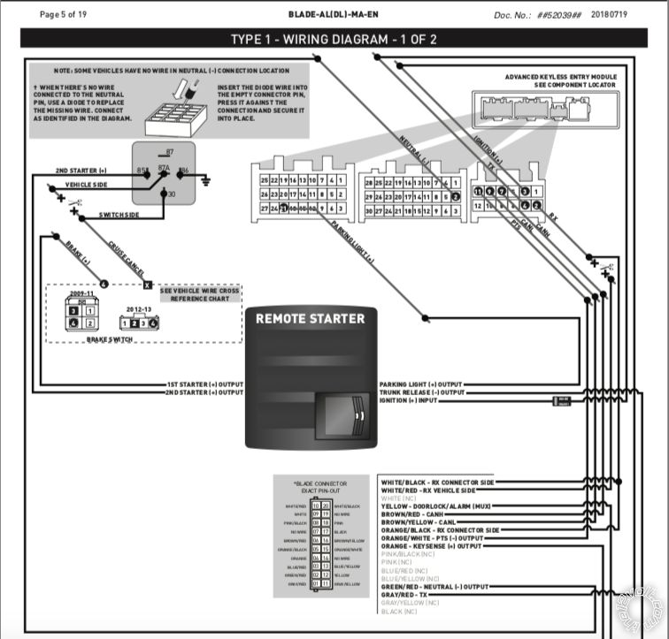
Hi everyone. I was trying to install my CM7200 + Blade AL yesterday on my Mazda 6 2009 PTS AT but for some reason, after having my all connections done according to the idatalink blade Al wiring diagram (specified for my car) and programming it by Klone firmware RS won't start my car anyway. After programming procedure the LED indicator on a blade turned off and keep being off even after clicking 3x lock button using my OEM key.
(Green loop was cut before installation process)
Any suggestions about what could be wrong with it? Maybe I should connect some additional wires that's not on a diagram or to do some additional steps? Thanks.
yarishov 
Member - Posts: 5
Member spacespace
Joined: January 05, 2020
Location: Illinois, United States
Posted: January 05, 2020 at 5:14 PM / IP Logged Link to Post Post Reply Quote yarishov
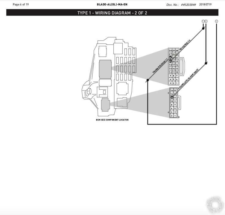
2009 Mazda 6 PTS AT, CM7200, Blade AL -- posted image.
yarishov 
Member - Posts: 5
Member spacespace
Joined: January 05, 2020
Location: Illinois, United States
Posted: January 05, 2020 at 5:28 PM / IP Logged Link to Post Post Reply Quote yarishov
So, basically I connect everything like on this diagram (except trunk release- wire) + 12v constant, accessory, and ground wires. Do I need to connect something more? (Like GWA, status or Tach IN wire from a CN5 grey connector)
kreg357 
Platinum - Posts: 7,783
Platinum spaceThis member has made a donation to the12volt.com. Click here for more info.spaceThis member has been recognized as an authority in Electrical Theory. Click here for more info.spaceThis member has been recognized as an authority in Mobile Security and Convenience. Click here for more info.spacespace
Joined: January 30, 2009
Location: Pennsylvania, United States
Posted: January 05, 2020 at 6:42 PM / IP Logged Link to Post Post Reply Quote kreg357
Not sure I understand your current wiring but...
The Type 1 diagram does not show all the needed CM7200 wires.
First, I would use CN1 thick high current wires. The diagram says you need two (+) Starter wires so you would need to set the internal jumer to Starter so that the CN1 Blue wire at Pin 5 would be the second Starter wire. The CN1 Green IGN wire would be cut and the 1N4001 diode added on, then a 20 guage wire soldered on to the diode to connect to the vehicles Ignition wire as shown. So the only wire on CN1 you would not be using is the White wire. Black goes to Chassis Ground and Green/White would go to (+) Parking Lights. Being as you are not using too much current, I would combine the two +12 V Constant wires into one and fuse it down to 20 Amps. Find a good source for this wire like the relay block to the right of the OBD2 plug. Should be a white 4 pin connector. Use the Red/Blue or Red/Black wire.
Was the Black/Red Neutral wire at Pin 2? If not you have to use an inserted diode for that connection, stripe towards the R/S.
Not much else needs to be connected. The Blade supplies the Brake, Tach and Hood Pin.   
The CM7200 default is Engine Sensing = Tach. You should do a Tach Learn after Blade vehicle programming.
Soldering is fun!
yarishov 
Member - Posts: 5
Member spacespace
Joined: January 05, 2020
Location: Illinois, United States
Posted: January 05, 2020 at 8:12 PM / IP Logged Link to Post Post Reply Quote yarishov
Hi kreg377
Thanks for response
So yes, I did everything almost exactly like you said except:
I choose (by jumpers) Blue for a Parking and Green/White - Starter 2
And also I connect White wire to the Accessory (Pink/Yellow wire - relay block right of obd )
And no, I dont have any Black/Red neutral wire in my car's socket so to connect my neutral wire from my CN4 I just used a pin terminal connector to have it nice and secure like OEM (bcz if I originally have that Black/Red neutral wire in my car- I would probably need to connect mine to it without any diod, right? - that's why I think that this diod here works more like a connector pin than a diod overall)...Or that diode could be a reason why it won't start?
And yes, Everytime when I'm trying to do a tach learning process I don't have any results at all. (Start the vehicle, hold the foot brake and activate the remote start by holding the lock button on my OEM key for 3 second). According to the instruction the parking light must flash once but I have nothing at all...
kreg357 
Platinum - Posts: 7,783
Platinum spaceThis member has made a donation to the12volt.com. Click here for more info.spaceThis member has been recognized as an authority in Electrical Theory. Click here for more info.spaceThis member has been recognized as an authority in Mobile Security and Convenience. Click here for more info.spacespace
Joined: January 30, 2009
Location: Pennsylvania, United States
Posted: January 05, 2020 at 9:22 PM / IP Logged Link to Post Post Reply Quote kreg357
I would follow the diagram and delete the ACC connection you added.
Did the entire Blade programming procedure go as per directions?
I don't see any mention of this being a 3X Lock type of solution. Do you have an antenna kit with remotes connected to the CM7200? Tach programming is always done with a Compustar remote and its' engine START button. I've never seen where you can use a factory remote to do a Tach Learn.
Soldering is fun!
yarishov 
Member - Posts: 5
Member spacespace
Joined: January 05, 2020
Location: Illinois, United States
Posted: January 05, 2020 at 10:01 PM / IP Logged Link to Post Post Reply Quote yarishov
Ok, will be done
Yes, everything went smooth - after the all steps and exact amount of blue led flashing (according to the programming procedure for my car) the blade LED turned off and still being like that.
Oh,now I see where is my problem- for some reason I think that if I used a Klone firmware - from that moment I will need just my OEM key to operate everything in my RS (tach in procedure, remote start) I didn't know that I suppose to have one more key from Compustar to basically use it just for a tach in procedure :) what's is the point in Klone firmware at all then?) I will need to have a two keys anyway, so basically it's not a big deal if I suppose to leave one incide my remote starter or keep it in my bedroom under the bed ;)
Thanks for a help kreg357. Appreciate it 👍. Let me order that additional key then and see if it fix my problem.
kreg357 
Platinum - Posts: 7,783
Platinum spaceThis member has made a donation to the12volt.com. Click here for more info.spaceThis member has been recognized as an authority in Electrical Theory. Click here for more info.spaceThis member has been recognized as an authority in Mobile Security and Convenience. Click here for more info.spacespace
Joined: January 30, 2009
Location: Pennsylvania, United States
Posted: January 06, 2020 at 7:17 AM / IP Logged Link to Post Post Reply Quote kreg357
The KLON process is not to allow the vehicles factory remote FOB to replace a R/S remote. The KLON process is necessary to capture, manipulate and download the factory immobilizer chip info onto the bypass module for remote start bypass functions. The newer 80 bit and higher encryption needs remote computer support to handle this process.
There is some terminology that might be confusing the issue. The Compustar remotes are not keys and can not be used alone to PTS the engine. They only provide RKE functions and have a button to remotely start the engine. You still need the factory FOB to drive the car and PTS it.
If you did not get a Compustar Remote Kit that includes the remotes and the antenna harness and antenna, you need one.
Soldering is fun!

If you wish to post a reply to this topic, you must first login.
If you are not already registered, you must first register.

  Printable version Printable version Post ReplyPost New Topic
You cannot post new topics in this forum
You cannot reply to topics in this forum
You cannot delete your posts in this forum
You cannot edit your posts in this forum
You cannot create polls in this forum
You cannot vote in polls in this forum

  •  
Search the12volt.com
Follow the12volt.com Follow the12volt.com on Facebook
Thursday, May 2, 2024 • Copyright © 1999-2024 the12volt.com, All Rights Reserved Privacy Policy & Use of Cookies
Disclaimer: *All information on this site ( the12volt.com ) is provided "as is" without any warranty of any kind, either expressed or implied, including but not limited to fitness for a particular use. Any user assumes the entire risk as to the accuracy and use of this information. Please verify all wire colors and diagrams before applying any information.

Secured by Sectigo
the12volt.com spacer
Support the12volt.com
Top
the12volt.com spacer